Deep Sleep Shield Update
-
Hi Pycom Community!
A quick update to let you know, we're expecting to receive the Deep Sleep Shields early this week and will have them shipped out to you shortly afterward!
The Deep Sleep feature will work in a very similar manner to how the Pytrack and Pysense initiate their deep sleep modes; you'll need to use a MicroPython library specifically for the Deep Sleep Shield (https://github.com/pycom/pycom-libraries/tree/master/deepsleep). Please note, that as with all of our libraries, this library is subject to change for new features/updates in the future, so check back for updates!
Thanks for your patience, we can't wait to see what you get up to with your devices! Share your projects with us on the Forum, Twitter, Hackster or drop us an email!
All the best,
The Pycom Team
-
@lambda280
I am using @Butch 's BME280 lib from HEREIf I can get away with using P10 sequentially I will. Moving SCL to another pin is a great alternative. My BME280's are pretty close, about 5cm, but they are plugged into the LoPy expansion shield pin headders, which have some 'play' in them (not a solid connection). I would prefer to solder them somewhere for impact testing. What's hot glue for anyway :-)
I'm using a fully made breakout BME280 board from HERE
@jmarcelino thought moving the I2C pins is best, since you can't move the deep sleep shield pin 10. -Thank you!
in the main.py I added the pin assignment:
i2c = I2C(0, I2C.MASTER, baudrate=100000, pins=('P8','P9'))Works fine now.
-
@ledbelly2142 My code extends the BME280.py driver linked to in this forum (a pythonized version of existing c++ drivers). The gist is given in the pycom documentation for I2C - you pass in a tuple for the "pins" keyword:
i2c.init(I2C.MASTER, baudrate=100000, pins=('P8', 'P9'))
In this example, 'P8' being the SDA line, 'P9' being the SCL. I happen to be using those two at the moment as they simplified routing on my mating PCB. I was using ('P9','P8') prior to this and they work fine, just make sure they are connected to the corresponding pins on the BME280. I don't believe "any" pin combination will work - you either have to get familiar with the ESP32 and the pins in use by the LoPy, or just use trial and error, or my case, trial and smoke.
I needed to drop the baud rate to 100K to work with the BME280 (Embedded Adventures). I have ~ 10 cm of wiring between the LoPy and BME - perhaps that is why. When working with I2C, it is helpful to have a device you are very familiar with to debug your connection setup, then switch in the new driver and sensor. Going step by step and using the REPL is your friend in this regard.
-
@lambda280
Thanks for your response.
I am also using a BME280. What did you do to use P8 for SCL?Did you edit the I2C lib or redefine the pin in your main.py?
-
@ledbelly2142 P10 is communicating with the PIC that yanks power off/on to the WiPy/LoPy via Q1. (see schematic - hope I am not teaching grandma how to suck eggs)
I could not make both work at the same time, but I did not try unloading the deepsleep module for sequential operation with I2C. Instead I moved SCL from P10 to P8 which works fine. In addition, I had to spin my mating PCB to use P8 (grr).
In general, more explanation of the Deep Sleep Shield's design and inner working would be helpful for folks like myself that are not hardware savvy. I've seen a fair number of forum posts that begin with confusion about how the shield works and what can't be done when using it.
I have been running a 3V3 BME280 I2C sensor and have seen no issues from power cycling with deepsleep operation. The system has been in continuous operation for a few weeks, power cycling every minute. Initially I had brownouts when the LoPy booted with sensor loads attached (I2C and others) to the LoPy 3V3 pin. A cap on the 5V and 3V3 did not help ( appears to be a ESP32 issue with the brownout detector), so I added a high side switch to sequence power to the sensors, similar to the shield. If you don't see the brownout detector firing - it is not needed.
I think some of the shortcomings of the deepsleep implementation could be addressed with the PIC code - I have not found the source for the PIC - another post discusses reverse engineering the code so I suspect it is not available. I'd rather replace the deepsleep hardware design and eliminate the PIC or move to the OEM module, than try to reverse the PIC code. TI and others make IC's specifically for this use case.
Overall I am pretty happy with the shield as a countermeasure - I can always use a bigger battery/solar panel if the sleep current is still too high. Would help to understand it better.
-
There seems to be a conflict with the deep sleep lib and I2C, both use pin 10. Can the deep sleep shield be used with another pin?
Should they be used sequentially, one after another to re-purpose pin usage?
For example, sequential logic would be:
- LoPy turns on
- use pin 10 for I2C's SCL
- after reading, use pin 10 for deep sleep
- on wake, restart logic flow
Does this have any implications (potential damage) for sensors connected to I2C bus?
-
I have not yet received my Deep Sleep Shields from my old orders :(
-
I was a late comer to adding my name for getting a deep sleep shield for my LoPy. I did the survey monkey survey. How can I tell if Pycom has me on their list of folks to send shields to?
-
Got my shield last week, thank you!
-
@Colateral
It's needed because the deepsleep current was high on the LoPy (the L01 OEM module is fine): https://forum.pycom.io/topic/1022/root-causes-of-high-deep-sleep-current/1
-
What is the purpose of this deepsleep shield? Is it required for LOPY and LOPY OEM?
-
@dClaus Ahh ok yep - I'll get this changed! Thanks for the advice!
-
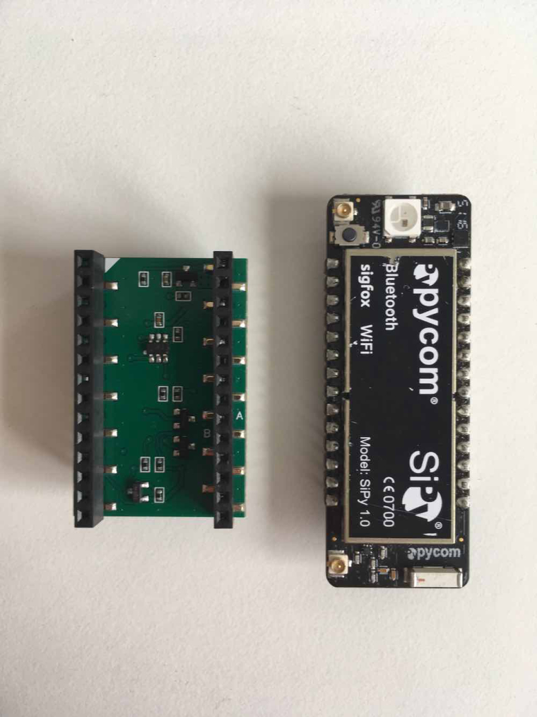
@bucknall Thanks for the pictures.
The deep sleep shield picture in the documentation must by like this, with the little 6 pin component on top center and the 2 twins components (3 pins) at bottom right !
Can you change the documentation picture ?
Thanks for all the documentation readers.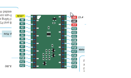 .
.
-
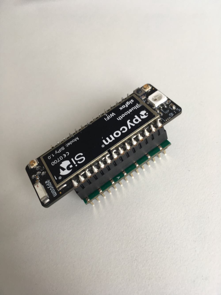
@dClaus I'm a little unsure of what you are asking but here's an image of how a SiPy and Deep Sleep Shield should be aligned.
-
@bucknall When I am looking at the components on the "Deep Sleep Shield" in the documentation and on my shield, i will say that the white triangle is near the P13 pin. In the documentation i also read align the white triangle on the Shield with the LED of the Pycom Device, that means that the white triangle must be near the reset pin. There must be an error in the picture (180 degrees rotation) or an error in the explanation.
The white triangle near the reset pin from the Pycom Devises (also near the led), is this not the correcte response ?
-
@livius
From what was shared at the Eindhoven hackaton the FiPy doesn't have that issue, I guess that's the one coming soonest (maybe within the next month or do going by the KS updates)
-
@bucknall
May i ask if there is a plan for new developement boards e.g. Wipy3 that do not need deep sleep Shield?I know that OEM modules are not affected - but many times "dev" boards are really usefull for final things and in many scenarios are used without any custom board.
-
The shields arrived Friday here in Germany!
Many thanks for them since i can now start with the battery powered devices!
-
@dClaus The triangle should align with the LED on your Pycom Device - I'll update the docs with pictures to reflect this!
-
Hello,
Can you confirm me that the correcte monting of the "Deep Sleep Shield" is with A and B letters at the power and GND side and the white triangle near the reset pin ?
Thanks