SI7021 I2C pin setup (SOLVED)
-
Hello everyone, I have tested with an HTU21d sensor that is very similar to the SI7021 and with the SI7021 class I also get the "I2C bus error". However with the code in the main.py, it works perfectly, and without external resistances, I do not understand why I get the error with the class, if everything seems to be fine.
I use this one:from machine import I2C import time i2c = I2C(0, I2C.MASTER) print(i2c.scan()) #I get [64] is 0x40 i2c.writeto(0x40, 0xf3) #read temp no hold time.sleep_ms(25) temp = i2c.readfrom(0x40, 3) temp2 = temp[0] << 8 temp2 = temp2 | temp[1] print((175.72 * temp2 / 65536) - 46.85)I hope it helps you, Regards
-
@eric73 said in SI7021 I2C pin setup:
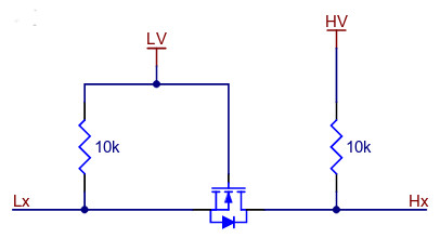
Single transistor level shifter ?
Yes. there is a standard circuit doing this with single MosFET transistor, used by all cheap level shifter. Principle below. LV is low voltage, HV is high voltage, Lx and Hx are the low & high voltage logic. And you see the pull-up resistors on both sides:
P.S.: You could make a picture of the back side of the sensor, just to clarify @Eric73 's question.
-
@tttadam Single transistor level shifter ? A single transistor is an inverter gate, your SDA and SCL signal will be inverted. Please note that i2c is an opendrain bus with pull up. Your SI7021 can be powered by +5V (if its identical to the one showed by robert-hh) but have you checked is your board have 5V-3.3V regulator and have you checked what is SDA and SCL voltage level when you just power SI7021? In SI7021 datasheet absolute maximum rating for SDA and SCL is 3.3V, i have doubts that a SI7021 board have +5V pull-up on SDA and SCL....without power any of the two board, please check your wire continuity with multimeter if you can.
-
@robert-hh Well I just ran the code again(from 5V without resistors), but I got OS error for every baud rate from 1 to 10000. So I think something most be wrong with this sensor.
-
@tttadam I searched a little bit for a module that looks like yours. I found one, and in the backside pictures I see some resistors, which most likely are 10k pull-up resistors, and a three terminal device, which is according to the print-out a LM6206N3 3.3V voltage regulator. The pull-up resistors seem to be connected to 5V. Being 10k, that should not hurt the pycom device, and you do not need external pull-up resistors. And the 5V were OK for your device.
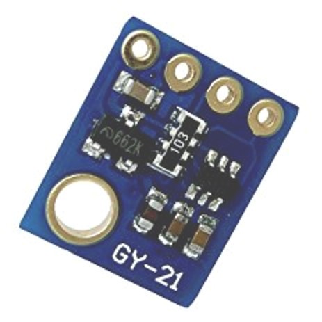
Edit: I see also a dual level shifter, which is intended to connect a 5V side at the micro to the 3.3 V side of the sensor. It is a single FET transistor level shifter.
-
@robert-hh Okay, I will get bigger resistors, and replace the sensor.
Thank you for the help.
-
@tttadam 1K is too low. The usual recommendation is 4.7 k. But that should not change the figure. The question is, whether i2c.scan() returns [64] also in the context of your main code.
If yes, then the port & wires & I2C protocol are OK, and we have to look at the SI7021 module.
-
@eric73 @tttadam So is it this code:
from time import sleep_ms
from machine import Pin, I2C

# Default Address
SI7021_I2C_DEFAULT_ADDR = 0x40

# Commands
CMD_MEASURE_RELATIVE_HUMIDITY_HOLD_MASTER_MODE = 0xE5
CMD_MEASURE_RELATIVE_HUMIDITY = 0xF5
CMD_MEASURE_TEMPERATURE_HOLD_MASTER_MODE = 0xE3
CMD_MEASURE_TEMPERATURE = 0xF3
CMD_READ_TEMPERATURE_VALUE_FROM_PREVIOUS_RH_MEASUREMENT = 0xE0
CMD_RESET = 0xFE
CMD_WRITE_RH_T_USER_REGISTER_1 = 0xE6
CMD_READ_RH_T_USER_REGISTER_1 = 0xE7
CMD_WRITE_HEATER_CONTROL_REGISTER = 0x51
CMD_READ_HEATER_CONTROL_REGISTER = 0x11

class SI7021(object):
  def __init__(self, i2c=None):
    self.i2c = i2c
    self.addr = SI7021_I2C_DEFAULT_ADDR
    self.cbuffer = bytearray(2)
    self.cbuffer[1] = 0x00

  def write_command(self, command_byte):
    self.cbuffer[0] = command_byte
    self.i2c.writeto(self.addr, self.cbuffer)

  def readTemp(self):
    self.write_command(CMD_MEASURE_TEMPERATURE)
    sleep_ms(25)
    temp = self.i2c.readfrom(self.addr,3)
    temp2 = temp[0] << 8
    temp2 = temp2 | temp[1]
    return (175.72 * temp2 / 65536) - 46.85

  def readRH(self):
    self.write_command(CMD_MEASURE_RELATIVE_HUMIDITY)
    sleep_ms(25)
    rh = self.i2c.readfrom(self.addr, 3)
    rh2 = rh[0] << 8
    rh2 = rh2 | rh[1]
    return (125 * rh2 / 65536) - 6
Form the first glance, it looks Ok and compatible to Pycom's MicroPython.
-
@eric73 I am using a 1k resistor both on SDA and SCL.
The program takes much more time to run because of the i2c.scan().... But I will write ehen I have the result.
-
@robert-hh link you looking for is in tilte https://forum.pycom.io/topic/648/si7021-i2c-sensor not ?
@ttadam Have you add pysical pull up resistor on SDA and SCL to 3.3V (4.7K or 1K value) ? Even if you set software pull up to the pin definitions, when you call i2c.init i dont know if pin your specify are not setup as pure opendrain by i2c library, so perhaps a test can with pull up can be done ?
-
@tttadam That#s strange, especially since i2c.scan() works, which also needs I2c communication. You could try to add an i2c.scan in the test after the i2c.init, just to confirm that it works. And yes, you do not need every baud rate. You can go back to a value like 100000.
I faintly recall a link to the SI7021 driver you are using, but cannot find it any more.
-
Okay I modified the code as you recomended it.
But I got the same error on every baudrate.
Here is the csv, but nothing intresting in it: http://www.filedropper.com/data_11import pycom from machine import I2C, Pin from SI7021 import SI7021 import time expledpin = Pin('G16', mode=Pin.OUT) buttonpin = Pin('G17', mode= Pin.IN, pull=Pin.PULL_UP) i2c = I2C(0, pins=("P9","P10")) start = True while start: if buttonpin() == 0: start = False with open("/sd/data.csv", 'a')as ds: expledpin.value(1) for baud in range(1, 115200): pycom.rgbled(0x0000FF) i2c.init(I2C.MASTER, baudrate=baud) sensor = SI7021(i2c=i2c) try: print(sensor.readTemp()) ds.write("\n\r;;"+str(sensor.readTemp())) pycom.rgbled(0x00FF00) except OSError as er: pycom.rgbled(0xFF0000) expledpin.value(0) ds.write("\n\r"+str(repr(er))+";"+str(baud)+";") expledpin.value(1) time.sleep(0.001) pycom.rgbled(0x000000) ds.close()
-
@tttadam You do not have to re-create the i2c object. You can call i2c.init() to change the parameters. And I still do not know why you create the Pin objects separately. You just have to name them when creating the I2C object:
bus = I2C(0, I2C.MASTER, baudrate=baud, pins=("P9","P10"))
The init method of i2c will initialize the Pin objects.
-
I created a small code so it looped through all tha baudrates. Maybe a little overkill.
Off topic, but the code sometimes freezed for a half a minute or so. It was because I was created to much i2c object, and a garbage collector kicked in? Can I prevent that behavior?
Also If you can give any feedback for my code I would appreciate it very much.Anyway this code was unsuccessful. I was unable to find a the correct baud rate, I got the same I2C bus error always.
import pycom
from machine import I2C, Pin
from SI7021 import SI7021
import time

pin9 = Pin("P9",mode= Pin.OPEN_DRAIN, pull= Pin.PULL_UP)
pin10 = Pin("P10",mode= Pin.OPEN_DRAIN, pull= Pin.PULL_UP)
expledpin = Pin('G16', mode=Pin.OUT)
start = True
buttonpin = Pin('G17', mode= Pin.IN, pull=Pin.PULL_UP)
while start:
    if buttonpin() == 0:
        start = False


with open("/sd/data.csv", 'a')as ds:
    expledpin.value(1)
    for baud in range(1, 115200):
        pycom.rgbled(0x0000FF)
        bus = I2C(0, I2C.MASTER, baudrate=baud, pins=(pin9,pin10))
        # bus = I2C(0, I2C.MASTER, baudrate=100000, pins=("P8","P7"))
        sensor = SI7021(i2c=bus)
        try:
            print(sensor.readTemp())
            ds.write("\n"+str(sensor.readTemp()))
            pycom.rgbled(0x00FF00)
        except OSError as er:
            pycom.rgbled(0xFF0000)
            expledpin.value(0)
            ds.write(str(repr(er))+str(baud))
            expledpin.value(1)

        time.sleep(0.001)
        pycom.rgbled(0x000000)

    ds.close()
-
@tttadam So it means that at least the i2c protocol is now working. 64 or 0x40 ist the proper i2c address of the device. Try to reduce the baud rate.
-
@robert-hh Yes.
for i2c.scan() i get back this: [64], but I2C bus error for print(sensor.readTemp())
-
@tttadam did you try swapping sda and scl again when running with 3.3v?
-
@eric73 Well, you are right. I gave the sensor 5v instead of 3.3. I think I killed it.. well least a learned something. I also tried with 10k resistor but still getting I2C bus error...
Thanks for the help anyway.
-
@tttadam Definitely Vcc should be 3.3 V. And I cannot tell whether pull-up resistors are present on the board. Adding some with a value of about 4.7 - 10 kOhm should not hurt.
-
@tttadam Strange things, i have a look to your wire connexion, i hope my eyes are wrong but it seem you power your sensor with VIN (approx 5V), but your device SI7021 have +3.6V maximum power supply voltage so +5V can destroy your device.
If i take time to watch your wire it because typically on a scan i2c your device seem to ACK all address starting by 0x40 (64) and this can be happen in case of bad gnd connexion, please check your power supply +3.3V and GND for your SI7021.
If you have an oscilloscope for probin SDA and SCL this will be very helpfull.