UART Reading Serial Stream - Escape Sequences
-
Hello,
I am trying to read the serial output from a LV-MaxSonar distance sensor, using UART.
From the datasheet, I read that :"Pin 5-TX- delivers asynchronous serial with an RS232 format, except voltages are 0-Vcc. The output is an ASCII capital “R”, followed by three ASCII character digits representing the range in inches up to a maximum of 255, followed by a carriage return (ASCII 13). The baud rate is 9600, 8 bits, no parity, with one stop bit. "
I currently have the following code running, to just 'see' what's being received on the serial:
uart1 = machine.UART(1, baudrate=9600, bits=8, parity=None, stop=1)
while True:
    print(uart1.readall())
    time.sleep(1)
But the result of running this code, reading data from the sensor is:
b'\x06gdy+\x06g\xac\x00+\x06gcy+\x06gcy+\x06\xb3V\x00+\x06\xb3V\x00+\x06dgy+\x06dgy+\x06dgy+\x06dgy+\x06dgy+\x06dg'
b'y+\x06dgy+\x06dgy+\x06dgy+\x06dgy+\x06dgy+\x06dgy+\x06dgy+\x06dgy+\x06dgy+\x06dg'
b'y+\x06dgy+\x06dgy+\x06dgy+\x06dgy+\x06dgy+\x06dgy+\x06dgy+\x06dgy+\x06dgy+\x06'
b'dgy+\x06dgy+\x06dgy+\x06dgy+\x06dgy+\x06dgy+\x06dgy+\x06dgy+\x06dgy+\x06dgy+\x06dgy+\x06dg'
What am I looking at there?
- It looks like a bunch of escape sequences to me, which though does not match what I'd expect, from reading the datasheet.
- It seems that this data indeed comes in a pattern, as there's always a "+" sign, and '\x06' "hacknoledge character", and so on.
- It also seems that this data contains the measurement, in some way, as positioning the sensor farther or closer to a target, makes the stream change (like in the first line if the output above).
I would appreciate if anyone had any information, to point me in the right direction, to correctly read data from this sensor's UART interface.
-
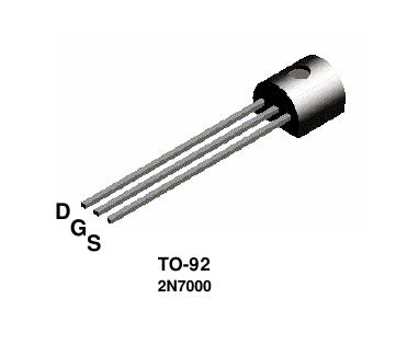
@spookyrufus It depends whthter you have a 736x or 738x model. When you operate the device from 3.3V, you shoul dbe able to connect the Serial out from the sensor directly to the Uart RX. If it is a 736x model, you'll need a Inverter, like you can do with a 2N7000: gate -> Sensor, Source -> GND, Drain -> RX, 10k Pullup-Resistor between RX and Vcc. You may also use an inverter chip, like 74hc04 ....
-
Transistor finally arrived (had to order it). Put it into place - solution works like a charm. Thanks Robert for the help, I appreciate it very much.
If some mod wants to mark the thread as [SOLVED], it'd be now good to do so. I tried doing it myself but could not find how to edit my thread's title.
-
@robert-hh I will definitely try the transistor way. I just received an answer from MaxBotix official support, and what they replied is as follows:
"We are not familiar with the Pycom microcontrollers, however, we have seen similar issues on the Raspberry Pi. It appears that you need a serial inverter (RS232 to TTL) to interface with this microcontroller. Implementing a serial inverter should solve the issue you are seeing. "
Which I believe is compatible with what Robert is saying .
-
@tmz I would strongly object to use that solution, for a few reasons:
a) If by bad luck you connect the RS232 out to the LoPy/WiPy in, you might damage the LoPy, because RS232 out levels are +/-5V .. +/-12V, which is definitely outside the permittet range of -0.3 .. 3.6 V for inputs.
b) the logic levels of the converter on the RS232 input side do not match the 0..5V range. It may works, but could not be relaible.
c) price. A 74HC04 cost < 50 cent, a single transistor 10..20 cent, and available at almost every electronic shop. The board you show is 6$ + shipping. The single transistor could be directly attached to the Sonar board; no extra wiring.
-
@tmz Hi thanks for the reply. Does this mean that you are powering your sensor with 5V then?
-
Hi, @spookyrufus i have the same issue reading MaxSonar sensor on LoPy with Expansion board. The solution is using RS232 converter IC https://www.sparkfun.com/products/11189
-
@robert-hh Thank you Robert. I appreciate very much you taking the time to explain me. I would have never figured out the issue myself, and still can't quite wrap my head around why they would decide to invert the serial signal on the sensor.
-
@robert-hh Since in UART mode the input has a Pull-Up resistor, a single Transistor like the 2N7000 or the like should do it. The transistor has three legs, called D (Drain), S (Source) and G (Gate). Connect S to GND, D to the UART input (P4) and G to the sensor output. I verified that with a Pulse generator, and the waveform is in spec.
-
@spookyrufus The inverter is sufficient. I just see I have a different module. It just looks similar.
-
@robert-hh OK, thank you. So by putting a 74HC04 in between the sensor and the LoPy, would I still need to shift 7 bits to the right via software, or is the 74HC04 sufficient to correct the issue?
-
@spookyrufus No, you cannot do that by software, at least not using the UART, since the uart already decodes the bit stream wrong. You could try to do the decoding using the getpulses() method to get the raw data and decoding the bit stream yourself. In a single message mode, that would start with a rising edge, and then you would have to do some bit fiddling. In grey history, I did that once, but now I would prefer to insert an inverter.
of the 74hc06, you just need one inverter. You could also use a 2n7000 transistor and an resistor.
-
@robert-hh Thank you Robert, I think I understand better now. I checked the datasheet for 74HC04 and it seems to me that that is a kind of 6 bits NOT port? Wouldn't there be a way to solve this via software, since the issue seems to involve only flipping and shifting bits?
-
@spookyrufus Independent from the more, for the UART mode the esp32 expects the starting state is high voltage, and each character transmission starts with a low voltage period of 1/baud_rate s, in case of 9600 baud the would be about 104 µs. If at that device the start state is low, the esp32 would not see the begin of a character transmission until eventually there a 1 0 bit sequence of the data is transmitted, which then would be interpreted as the start bit of a byte.
Interestingly, if i take sequences from your output like 'gdy+' or hex 6664792b, invert that and shift it 7 bits to the right, I get something which ends in 33370D, which is ASCII "37\r". So this can be fixed by inserting an inverter in between, like a 74HC04, or a single transistor circuit.
-
@robert-hh Robert, I would appreciate very much if you could check, yes. I am not sure I fully understand the point you are making.
As my main field of expertise is software, could you simplify a bit the explanation of what I should check, and how should I go at fixing the issue? I thought the TX pin is always streaming data, but as I read now from the datasheet there is the possibility to have 'single measurements' sent, through UART. Do you mean that I should first trigger that mode, and then check the voltage on the pin 5, and expect it to be high, before I can expect good data through UART?
-
@spookyrufus From the description it looks as if the signal is inverted.
"If standard voltage level RS232 is desired, invert, and connect an RS232
converter such as a MAX232."
Since the receiver waits for a start bit, just inverting the received date will not result in the right values. You can check by measung the inactive analog voltage at the TX pin. For proper operation, it should be high. If low, the you have to invert the signal. I thing I have such an sensor in my drawer, so I could check this evening.
-
@jcaron Thank you for your input. I haven't tried yet, but I was thinking to try to read the same data with a UART-USB converter or something.
I am supplying 3.3 volts from the Vcc pin of the LoPy to the sensor. The analogue distance readings that I am getting out of it (when measured with a multimeter) seem to make sense, so I was hoping it wasn't a power related issue.Indeed I also see a pattern, but before going too deep trying to decode/hack it, I wanted to get some feedback from wiser minds on here, about these differences with respect to what the datasheet says.
-
@spookyrufus Have you tried connecting the sensor to another device? Also what voltage are you supplying to the sensor?
It does indeed seem like the 06 is the equivalent of R (52) and the + (2B) the equivalent of CR (0D), with the remaining 3 bytes the equivalent of the 3 digits, but I fail to see a relationship. It's not just negated or inverted, there's no consistent XOR pattern...