Optimal I2C pullup resistors
-
The typical failure point was ~47 lines from the end of my code. by adding i2c.scan() before that line, the problem 'went away' and ran for 12+ hours until I bricked it doing a firmware OTA update. Prior, it would fail after the first or second 5 minute wait period. I don't believe I've got anything in the code to trigger start/stop conditions.
# main.py -- put your code here! from network import LoRa import socket import ubinascii import struct import time import os import math import abpkeys import ustruct from machine import UART, I2C, Pin #from machine import I2C, Pin #added for si7021 rh sensor from si7021 import SI7021 #added for si7021 rh sensor uart = UART(1, 9600) # init with given baudrate uart.init(9600, bits=8, parity=None, stop=1) # init with given parameters #initialize i2c to link to rh sensor i2c = I2C(0, pins=("P9","P10")) i2c.init(I2C.MASTER, baudrate=9600) sensor = SI7021(i2c=i2c) # Initialise LoRa in LORAWAN mode. # Please pick the region that matches where you are using the device: # Asia = LoRa.AS923 # Australia = LoRa.AU915 # Europe = LoRa.EU868 # United States = LoRa.US915 lora = LoRa(mode=LoRa.LORAWAN, region=LoRa.US915) # create an ABP authentication params #my keys are stored in abpkeys.py then linked here so I have the same source running #on multiple devices dev_addr=abpkeys.dev_addr nwk_swkey=abpkeys.nwk_swkey app_swkey=abpkeys.app_swkey #dev_addr = struct.unpack(">l", ubinascii.unhexlify('xxxxxxxx'))[0] #nwk_swkey = ubinascii.unhexlify('xxxxxxxxxxxxxxxxxxxxxxxxxxxxxxxx') #app_swkey = ubinascii.unhexlify('xxxxxxxxxxxxxxxxxxxxxxxxxxxxxxxx') for i in range(0, 71): lora.remove_channel(i) print('Removed default channels') time.sleep(1) # Set US ISM 915 channel plan for TTN US lora.add_channel(0, frequency=903900000, dr_min=0, dr_max=3) lora.add_channel(1, frequency=904100000, dr_min=0, dr_max=3) lora.add_channel(2, frequency=904300000, dr_min=0, dr_max=3) lora.add_channel(3, frequency=904500000, dr_min=0, dr_max=3) lora.add_channel(4, frequency=904700000, dr_min=0, dr_max=3) lora.add_channel(5, frequency=904900000, dr_min=0, dr_max=3) lora.add_channel(6, frequency=905100000, dr_min=0, dr_max=3) lora.add_channel(7, frequency=905300000, dr_min=0, dr_max=3) #channel 8: 903900000 hz min_dr 0 max_dr 3 #channel 9: 904100000 hz min_dr 0 max_dr 3 #channel 10: 904300000 hz min_dr 0 max_dr 3 #channel 11: 904500000 hz min_dr 0 max_dr 3 #channel 12: 904700000 hz min_dr 0 max_dr 3 #channel 13: 904900000 hz min_dr 0 max_dr 3 #channel 14: 905100000 hz min_dr 0 max_dr 3 #channel 15: 905300000 hz min_dr 0 max_dr 3 print('US channels set') time.sleep(1) print('restoring LoRa NVRAM') lora.nvram_restore() print('Joining LoRa via ABP') # join a network using ABP (Activation By Personalization) lora.join(activation=LoRa.ABP, auth=(dev_addr, nwk_swkey, app_swkey)) # create a LoRa socket s = socket.socket(socket.AF_LORA, socket.SOCK_RAW) # set the LoRaWAN data rate s.setsockopt(socket.SOL_LORA, socket.SO_DR, 3) #Let's check whether the si7021 is attached and enable further code if it responds print('check si7021 serial') si7021presence=True temperature=-255 print(i2c.scan()) temperature=int(sensor.temperature()) relativehumid=int(sensor.humidity()) dewpoint=int(sensor.dew_point()) print('Temp',temperature) print('RH%',relativehumid) print('Dewpoint',dewpoint) try: temperature=int(sensor.temperature()) print('temperature = ',temperature) except NameError as msg: print(msg) si7021presence=False if( temperature !=-255): print('temperature reported = ',temperature) print('si7021 presence = ',si7021presence) #The first 5 seconds of dust data always seems irregular, so let's delay and clear the buffer data = uart.readall() time.sleep(10) data= uart.readall() time.sleep(1)# then give it another second for the next good byte to come in. while (1): readytosend=False print('polling Dust Sensor') data = uart.readall()# get everythitng from the serial buffer if data is not None:#make sure it'st not an empty buffer bytestream=data.split(b'BM')[1][0:31]# HPMA sends 32 byte packets that start with \x42\x4D ('BM') if len(bytestream)==30:#check tthat we actually got 30 bytes (excluding the data we split out) if bytestream[0:2]==b'\x00\x1c':#HPMA packet is always 28 data bytes(excluding start header and checksum) checksum=143#since split command removed the \x42\x4D, add them back to get correct checksum validated=0 for i in range(0,28): checksum+=bytestream[i]#cycle thru the data values and add them up validated=int(bytestream[28])*256+int(bytestream[29])#read checksum bytes from packet and make them a 2-byte integer if checksum==validated:# both values should match, else we have a corrupt packet pm25=int(bytestream[4])*256+int(bytestream[5])#these two bytes represent the particulate detected that's 2.5um large pm10=int(bytestream[6])*256+int(bytestream[7])#these two bytes represent the particulate detected that's 10um large print('pm2.5 = ',pm25) print('pm10 = ',pm10) readytosend=True else: print('checksum failed') else: print('invalid packet length') else: print('incomplete packet') if(si7021presence==True): print(i2c.scan()) print('poll temp') temperature=int(sensor.temperature()) print('poll RH') relativehumid=int(sensor.humidity()) print('poll Dew') dewpoint=int(sensor.dew_point()) if readytosend==True: # make the socket blocking # (waits for the data to be sent and for the 2 receive windows to expire) s.setblocking(True) print("Sending data!") # send some data # s.send(bytes([0x01, 0x02, 0x03])) #if(si7021presence==True): tempstruct=((ustruct.pack('>H',temperature))) rhstruct=((ustruct.pack('>H',relativehumid))) dewstruct=((ustruct.pack('>H',dewpoint))) s.send(bytes([bytestream[4], bytestream[5], bytestream[6],bytestream[7],tempstruct[0],tempstruct[1],rhstruct[0],rhstruct[1],dewstruct[0],dewstruct[1]]))#,relativehumid,dewpoint])) #else: # s.send(bytes([bytestream[4], bytestream[5], bytestream[6],bytestream[7]])) pybytes.send_virtual_pin_value(False, 0, (bytestream[4]<<8)+bytestream[5]) time.sleep(1) pybytes.send_virtual_pin_value(False, 1, (bytestream[6]<<8)+bytestream[7]) time.sleep(1) pybytes.send_virtual_pin_value(False, 2, temperature) time.sleep(1) pybytes.send_virtual_pin_value(False, 3, relativehumid) time.sleep(1) pybytes.send_virtual_pin_value(False, 4, dewpoint) time.sleep(1) #pybytes.send_virtual_pin_value(False,2,100) #time.sleep(10) print('saving LoRa NVRAM') lora.nvram_save() # make the socket non-blocking # (because if there's no data received it will block forever...) s.setblocking(False) print("receiving data!") # get any data received (if any...) data = s.recv(64) print(data) print("Go to sleep 5 minutes!") time.sleep(300)``` -
@dnear1 Hmm. I would still suspect the code fails to generate a valid Stop condition before starting the next addressing cycle. Maybe the problem is hidden at the end of dew_point() ?
Hook up a scope if possible and check for a valid start condition. That would also ease the problem of choosing good pull up resistors without wasting too much power. -
Digging further into my issues, it seems if I stuff a print(i2c.scan()) before I read an i2c device, it will reliably succeed;
if I don't , this is what i see on the scope.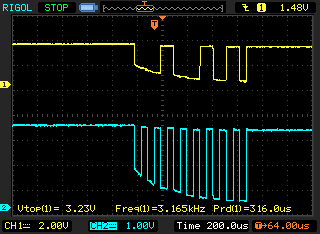
So my guess is the pullup is too strong?
-
I seem to get identical results regardless if I use a 1.5k, 4.7k or 6.8k resistor for the pullups.
-
@dnear1 Check the GND connection between the LoPy4 and the sensors, and also the oscilloscope. It looks like there is some inductivity in the way.
-
@robert-hh I'll try to shorten/redo the connections when I get a chance in the next few days.
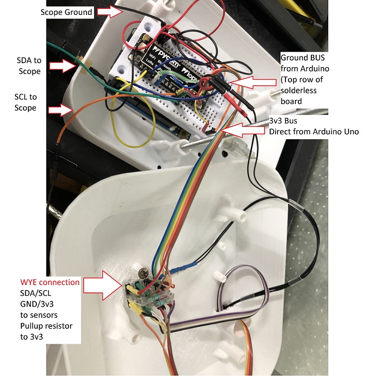
Ignore the wire colors, especially for the ribbon wire. The wires are organized by the color of the heat shrink tubing.
The Arduino board has the Atmega removed and is just being used to supply 5v to the Pycom and 3.3v to the sensors. The 3v3 output from the Pycom is unattached. Both share a common ground via two wires connected to the Arduino GND pins.
My design was constrained by the short length of the Pycom LoRa antenna cable and trying to make the sensor shields removable/serviceable. -
@dnear1 This wiring looks like calling for trouble. Especially breadboards have sometimes lousy connections. For anything but desktop test setups, better use soldered or at least screwed connections.
-
@robert-hh
I was hoping to resolve issues before spending time designing/building a PCB. I never had issues like this just using an Arduino Mini with solderless breadboards.I made new I2C wires with individual 24awg 7/32 strand, and wrapped a ground lead around the SCL and SDA pins separately, and did a daisy-chain configuration from the first sensor to the second. That alone didn't help.
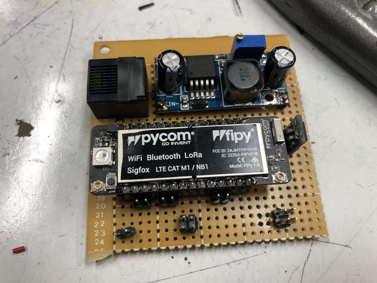
I started soldering together a test board that can draw power from a POE injector, since this will eventually get mounted on the roof, 4 stories up. This is as far as I got. The top PSU will feed 5.5v to the Pycom and the right-most will give 3.3v to the I2C sensors. It's assembled and the power supplies tested but needs to be swapped into the enclosure.
-
Could the pullups built into the sensors have been the problem all along?
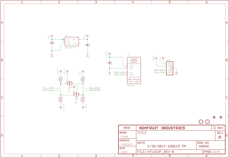
I was using a 3v3 IO so I only had 3v3 connected. On one of my assemblies, all 3 sensors (Adafruit HTU21d, Adafruit MPL3115A2 and adafruit TSL2561 breakout boards have these 10k pullups and the level shifter.
I soldered a jumper from 3v3 to vin on all 3 and removed the pullups below the Pycom, and things seem a lot cleaner..
-
@dnear1 Th elowest suitabel value of the pull-up resistors depends only on how much current the driving device can sink. For the ESP32 (20 mA) that would be ~165 Ohm, for the sensors you have to look in their data sheet. Per data sheet, pull-up resistors at the I2C bus can get down to ~1 kOhm. With all the 10k's and a voltage of 3.3 V it will be effetively ~1.7 kOhm. Even if that is not a problem, it cause higher currents in the GND line. And the Oscilloscope picture you showed indicated such a problem. Removing some of the transistors reduces the impact of the problem, but is not the cause.
-
@robert-hh Actually, I scoped it with the Vin and 3v0 pins tied together at 3v3 and both with/without the 1.7k pull-up on the main board, I was getting a clean signal with full swings from the start. Not only that, but I was able to increase the I2C speed from the meek 9600 baud to 100,000 baud without issues.
-
@dnear1 So what was the issue then with the scope diagram below: https://forum.pycom.io/topic/4263/optimal-i2c-pullup-resistors/5
That one does not look well.

Hello! It looks like you're interested in this conversation, but you don't have an account yet.
Getting fed up of having to scroll through the same posts each visit? When you register for an account, you'll always come back to exactly where you were before, and choose to be notified of new replies (either via email, or push notification). You'll also be able to save bookmarks and upvote posts to show your appreciation to other community members.
With your input, this post could be even better 💗
Register Login