TEROS 12 and SDI-12
-
@tttadam That link is the pulses_get function, not the library.
I'll post the library on github once it works.
-
@tttadam That one is OK. You need just one channel. LV to 3.3V, HV to 5V A1 to both RX and TX of the pycom device. B1 to the data line of the sensor.
You have still the task to make TX high impedance when you receive. So you can try:
a) to set up the UART to the desired mode, and then
b) init the PIN for TX as OPEN_DRAIN.
if that does not work, connect a diode (e.g. 1N4148 or 1N5711) between A1 of the level shifter to TX, such that the Cathode (the side with the bar) is at TX. That prevents the TX output from driving the signal when it is high. It still can sink the signal line.
-
Regarding Level shifter. Take a look at this one:
https://learn.sparkfun.com/tutorials/single-supply-logic-level-converter-hookup-guide/all
and 3.3V RS485 Converter:
https://eckstein-shop.de/RS485-Board-33V
-
@robert-hh Alright, my knowledge is not so strong in this area, so I accept your recommendtation, no RS485 and level shifter it is. Thank you for the advice.
So level shifters, I found this one.
This is what was in your mind? If so, how would you wire it?
-
@tttadam It's not clear to me if that is easier to use than simply a one transistor level shifter. And so I would not use that choice.
Besides that:
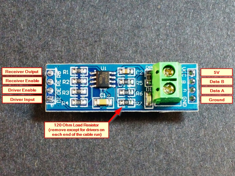
Receiver Output -> Pycom RX
The board operates at 5V, so you have to add at least a resistor of 4.7k to 10k between receiver Output and Pycom RX to protect the Pycom board.
Driver Input -> Pycom TX
Receiver Enable and Driver Enable can be switched together to a GPIO which is used to switch between receive and transmit.
Data A and B are the differential output/inputs. And that makes the trouble, since the sensor has not differential data interface. Thats why in the post I linked there is a 1.8V reference, to create a virtual differential signal.
5V and Ground are obvious.As said, I would prefer to connect RX and TX at the pycom device and connect it via a level shifter to the Sensor data line. You may need a pull-up resistor at the sensor to 5v, and in the software you will receive the commands that you have sent in addition to the response. In any case, it is not just plug and run.
The obvious advantage of the RS485 version is it's ability to drive long wires.
-
@robert-hh said in TEROS 12 and SDI-12:
@tttadam search for "RS485 TTL breakout board". Most of the are made for 5V at the UART side, but some too for 3.3V.
What I found is this sorry for the hungarian, but I need it ASAP, so I turned to local stores.
I also found this image on online. I think they are the same. But its still not clear how should I use it because it has 4 wire on both side.

Thank you for the help.
-
@tttadam search for "RS485 TTL breakout board". Most of the are made for 5V at the UART side, but some too for 3.3V.
-
@robert-hh said in TEROS 12 and SDI-12:
RS485
Can you recommend me a rs485 breakout board for pycom?
All I can find has an usb port on the end.
-
@tttadam The sensor in that link is a 3 wire device, but a RS485 adapter is used to connect it to the Pycom board. You do not have to do that, but that choice combines level shifting and connecting RX and TX to the sensor.
In any case, you need some kind of electronic adaptation, at least a level shifter and program logic to switch off the Pycom board's TX when you expect data from the sensor. You could try to set the UART output to OPEN_DRAIN, after you have init'ed the UART.
-
@robert-hh Yes I already saw that, but on my sensor there is only 3 wire (gnd, 5v and data)
And looks like in these example code there is 2 data wire.
-
@Pesien I think the github link in your forum thread is written in C.
how should I use it with micropyton board?
-
@thinginnovations Nope, I don't have any SDI 12 interface hardver, I hoped that I can use it directly with pycom without anything in the middle.
-
Try this link.
http://www.sdi-12.org/current_specification/SDI-12_version-1_4-Jan-10-2019.pdfThe h/W interface cct is towards the end of the document.
-
I´m working on a library to comunicate with SDI-12 sensors using a GPIO pin, but I have a problem with the pulses_get function because it seems to have a limit, so I can only read a max of 200 bits or 20 bytes for the SDI-12 sensor.
I posted it here: https://forum.pycom.io/topic/4829/does-pulses_get-function-have-a-200-bit-limitation-when-reading
Apart from that, It works.
-
@tttadam
Then you can use the seriel input and you don't need sdi 12. Just power on the the sensor and it will send the data one time.
-
@tttadam There was a discussion about that in the past on this forum: https://forum.pycom.io/topic/1924/sdi-12
-
@tuftec what kind of external hardver are we talking about?
-
SDI-12 is a very simple, half duplex serial protocol.
It should be extremely easy to impliment at the application level just using the USART as the communications device. You will need a little bit of external hardware to provide the physical interface.
-
Do you also have the SDI-12 interface to the pycom module? I've used similar SDI-12 devices on other hardware and it's on my todo list for the Lopy4 to port this over.
Andrew
-
just one TEROS 12