UART connection to 5TM soil moisture sensor
-
The sensor I'd like to read is capable of a bitbang serial connection:
It has got 3 wires GND, DATA, Vcc
How should I go about connecting it to the sipy and will I be able to read three sensors on different pins?
The sensors logic levels are as follows:
High 2.8 to 3.9 V
Low 0 to 0.8 V
Vcc = 3.6 to 12 V
How should i supply the sensors if they need to be powered up to get a reading from them?
link to the 5TM's integrators guide : https://www.ai-nex.co.jp/5TM-Integrators-Guide.pdf
-
@JackBasson I updated the script, taking into account that commands and responses and with CR-LF:
# SDI-12 send/receive snippet

from machine import UART
from time import sleep_ms


def setup_uart(num=1, pins=('P3', 'P4'), timeout=120, inverse=False):

    if inverse:
        uart = UART(num, 1200, pins=pins, bits=7, timeout_chars=timeout,
                    parity=UART.EVEN, invert=UART.INV_RX|UART.INV_TX)
    else:
        uart = UART(num, 1200, pins=pins, bits=7, timeout_chars=timeout,
                    parity=UART.EVEN)

    return uart


def sdi12_tx_rx(uart, tx_msg, send_break=True):

    if tx_msg is not None:
        if send_break:
            uart.sendbreak(14)  # Send the break char
            sleep_ms(5)  # Wait a little bit (may not be needed)
        uart.write(tx_msg + b"\r\n")  # Send the message
        # and wait until it has been sent
        # ESP has a long delay before sending data
        uart.wait_tx_done(int(len(tx_msg) * 10000/1200) + 30)
    # get the response back. It consists
    # of the message being sent (if any) and
    # the response.
    if tx_msg is not None:
        skip  = uart.readline()  # copy of the txmessage
    rx_msg = uart.readline()
    if rx_msg is not None:
        rx_msg = rx_msg.strip()
    # return the response only.
    return rx_msg
CR-LF will be added to the message and removed from the responses.
-
@JackBasson Here is a little script as starter.
For setup uart, you call:
uart = setup_uart([option])
one of the options for inverted UART would be:
invert=True
you may also have to try other
timeout=nn
values.
Then you can call:response=sdi12_tx_rx(uart, msg)
msg may be None. response contains the net message. it may be None, if nothing was received. You shoudl use an logic analyzer on the wire to check, if and what is transferred. The cheap 10USD Saleae clones from China are sufficient.
# SDI-12 send/receive snippet

from machine import UART
from time import sleep_ms


def setup_uart(num=1, pins=('P3', 'P4'), timeout=20, inverse=False):

    if inverse:
        uart = UART(num, 1200, pins=pins, bits=7, timeout_chars=timeout,
                    parity=UART.EVEN, invert=UART.INV_RX|UART.INV_TX)
    else:
        uart = UART(num, 1200, pins=pins, bits=7, timeout_chars=timeout,
                    parity=UART.EVEN)

    return uart


def sdi12_tx_rx(uart, tx_msg):

    if tx_msg is not None:
        uart.sendbreak(14)  # Send the break char
        sleep_ms(5)  # Wait a little (may not be needed)
        uart.write(tx_msg)  # Send the message
        # and wait until it has been sent
        uart.wait_tx_done(int(len(tx_msg) * 10/1.2) + 10)
        sleep_ms(10)
    # get the response back. It consists
    # of the message being sent (if any) and
    # the response.
    rx_msg = uart.read()
    # return the response only.
    if rx_msg:
        start_rx = 0 if tx_msg is None else len(tx_msg) + 1
        return rx_msg[start_rx:]
    else:
        return None
-
hi Robert thank you for your help, would you maybe please be able to provide us with example code on how to receive and send data?
-
@JackBasson Even if the circuit below is simple and works pretty well, I made a variant by replacing C1 and R4 by a pulse shaping circuit with CMOS gates. The remaing gate is used for the RX line:
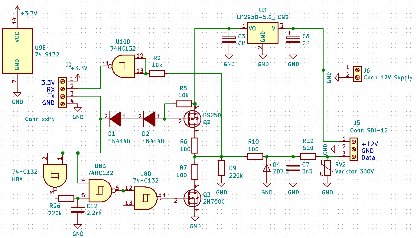
A 74Hc132 costs about 40ct, and the circuit has a better pulse shaping. Tests with 100nF load, equivalent to 400m total cable length, show a good pattern. Even 220nF load looked OK, equivalent to ~1000m total cable length.
P.S.: The other property of this diagram: Instead of the CMOS types, you can use bipolar plain vanilla npn and pnp types for the transistors.
-
@JackBasson @AndreBroekman I have made a breakboard test of the send section of the interface circuit below. Since I have not SDI-12 sensor here, I just connected a 47nF capacitor at the output. That should be equivalent to about 6 5TM sensors with a 30m cable each. The capacitive load is what may cause trouble.
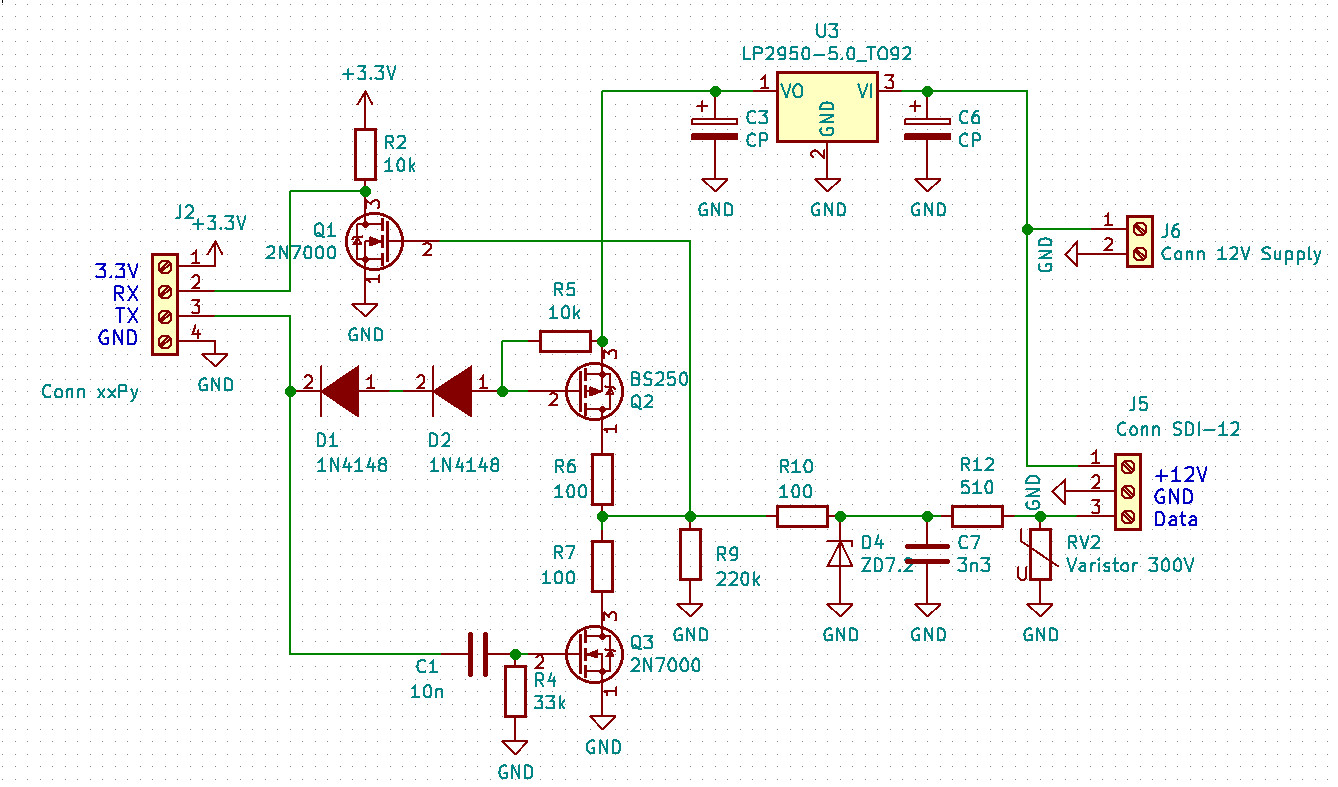
The circuit is a variant of which I posted earlier. It is inverting, so you can use the standard xxPy firmware. And the send section is high impedance when not sending. Q3 discharges the wire capacitance at the end of each bit for ~200µs. Below if a oscilloscope snapshot with a 47nF load at the output.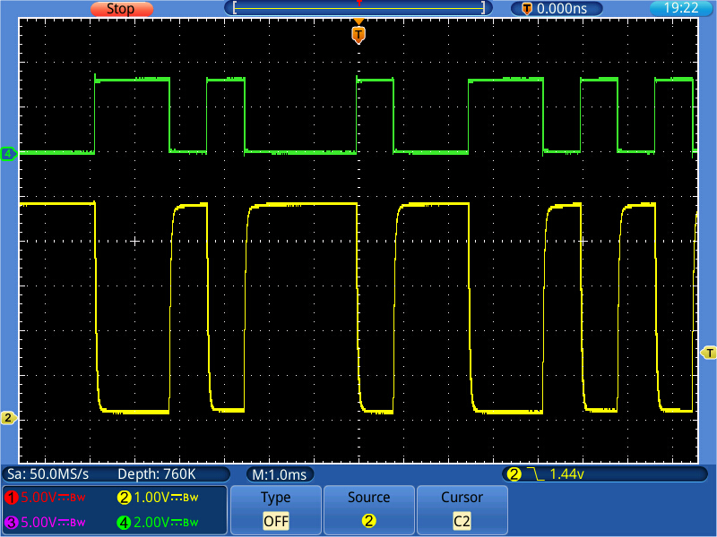
P.S.: In the test, I did not add the Z-Diode D4 and the varistor. These are protective elements against lightning overvoltage.
-
@AndreBroekman OK. So I fixed sendbreak(), such that it works fine in either mode. It turned out that I just had to replace two characters and to delete three. The tarball is uploaded again.
P.S.: If you are using an 74HC125 or 72HC126, you could use two spare gates as unconventional inverters. Then you would not need the modified firmware. Options, options, options, .....
-
@AndreBroekman Hello Andre. The tarball was created with the Pycom build system. You can use that directly with the Pycom Updater tools, option "load from file", to program the SiPy. You do not have to unpack it.
But just to be sure, that it is properly stored on ǴitHub, I downloaded and unpacked it here on my Debian system. No Problem.
About signal levels. The 5TM device which Jack mentioned seems just about fine with 3.3V signal levels.At least for a lab bench test it should work. Things are getting worse with long cables and multiple devices attached to the bus. Then you might get issues with transition times.
A bidirectional level converter - the one with the single transistor - will hardly work, as these only support low active signals, and then the rising edge of the signal is too slow. The rising edge is not actively driven. Since RX and TX at the SiPy are anyhow different pins, you do not need bidirectional level converters. A line driver like the 74HC125 or 74HC126 should be sufficient, which in addition you can switch off when not sending.Edit: The SDI-Protocol requires a break condition to be sent before a command of the data logger. There is a method for that in the UART module. The documentation for that is not immediately visible. You have to select the development version of the docs. https://development.pycom.io/firmwareapi/pycom/machine/uart/#uart-sendbreak
EDIT2: I just tested sendbreak. And it stops the inverted mode. Dang! So I have to add some bits to sendbreak.
-
@robert-hh Thank you @robert-hh for sharing the code! I did try to download and unzip the tarball but it appears as though the file header is either corrupt or missing (tried using 7zip on both Ubuntu and Windows). If you could kindly upload an alternative version that we could try downloading again.
When powering the SDI-12 sensors from a 5V rail (using an off-the-shelf buck-boost IC powered from the SiPy's 3.3V regulator), is a bi-directional logic converter necessary/recommended given the 3.3V logic of the PyCom architecture?
-
thank you very much for your advice.
-
@JackBasson I have added a tar ball with an SiPy firmware here: https://github.com/robert-hh/Shared-Stuff
It support UART inverse mode. To use it there is an additional keyword for the constructor or urta.init() call:
invert = signals
where signals is any of the keywords INV_RX, INV_TX, INV_RTS and INV_CTS, or'ed together, for instance:from machine import UART uart=UART(1, 1200, bits=7, parity=UART.EVEN, invert = UART.INV_RX | UART.INV_TX)For testing, you can connect the sensor data line directly to the RX pin, but the TX pin must be decoupled at least with a diode. Use a Schottky diode, Anode at TX pin, Cathode to the Sensor data pin. Without that diode, you can send, but will not receive the response from the sensor.
For the software you have to bear in mind, that you will also receive what you send, so you have to dismiss that data when receiving.
You found already the other thread about SDI-12. I had made some suggestions about interfacing there, which is not fully compliant. I will test an updated circuitry tomorrow and post the diagram.