SCT-013 current sensor
-
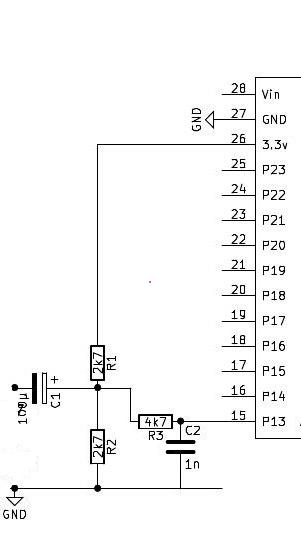
@StefanoF Using an optocoupler one can be in a partially analog mode. I tested it NOT with 230V AC, but with a lower voltage variable transformer and a signal generator. The circuit is below. For 230V R6 has to be about 390kOhm.
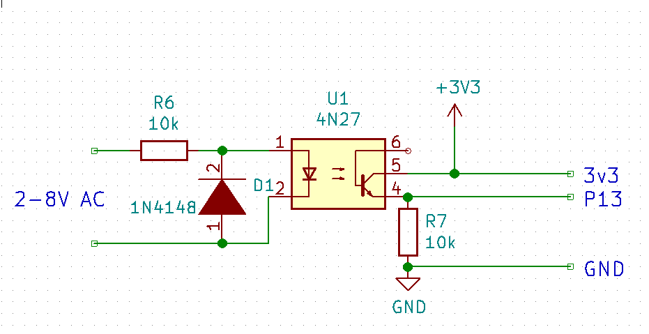
The signal at P13 is:
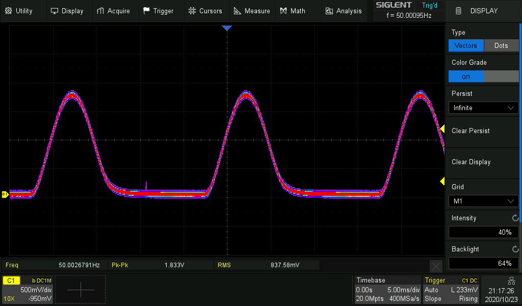
The picture shows color grading. The red area is the hot one which the trace most often passes. For the the picture the function generator was used as AC source.
I measured the result with the goertzel test script, which only looks at the 50Hz component of the signal. For a constant input voltage the output readings vary by +/- 1 %.
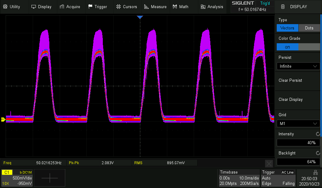
But the output varies a lot with temperature. Cooling down the optocoupler increased the output by ~30%.
Sample picture below. The pink area is the one the trace swept over during temp variation. The numbers displayed by the goertzel script went from ~120 to ~165.
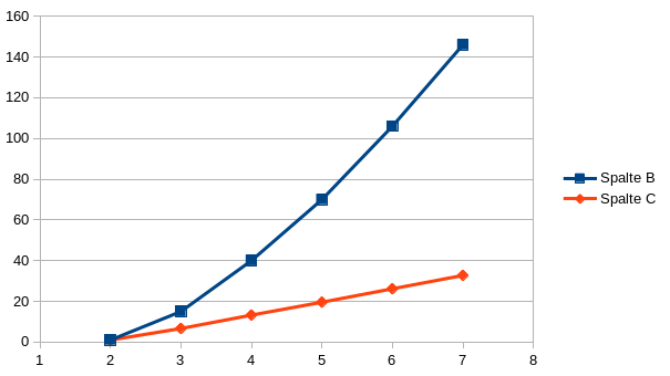
The Input/output transfer function is not linear. It is about Vout = x * Vin ** 0.7. But for a small range line 230V +/- 10% it's ok.
The blue line is Vin, the red Vout.
-
@StefanoF The problem is isolation against electric shocks. The ammeter is isolated as a complete box. There is no metal from the inside that you can touch (at least you should not). And it is electrically floating, which your device is not. So you need something for both safety and waveform transfer.
As initially said, you may also use an optocoupler. But the transfer characteristic is not linear, it changes with the temperature, and they are not made for analog mode. But still that may do. I can make tests for that and see, how that works.
-
@robert-hh
Hi,
Is there another alternative, just electronic components without transformer?
Example my electronic ammeter?

-
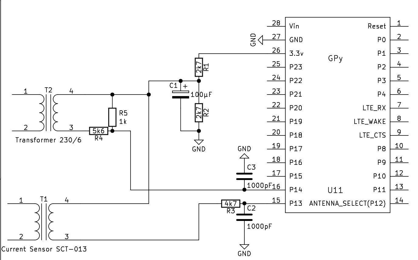
@StefanoF No. You cannot use anything from the SCT-013 sensor set-up, because this 1.65 reference point is derived from the regulated 3.3V supply. With two sources you could use a different interface circuit, but still you need a second "data" path for the 230V AC. I have attached a schematics which uses a common reference point for both signals. That is not my favorite one, but is simple and should work.
-
@robert-hh
I'm sorry, but not have space into my pcb , Can I use stc 013 variations set off 1.65 at empty?
Thanks a lot
-
@StefanoF The 5vDC is a regulated output. That is of no help for you. You need an unregulated 50 Hz AC output.
Unregulated - because it has to follow the fluctuations of the 230V mains,
50 Hz AC - because you need the phase information to calculate the power factor cos(phi) between voltage and current.
-
@robert-hh
Hi,thank for support,
into my project there is a transformer 220 to 5 v DC
what is the wiring diagram to measure the voltage for Lopy ?Thanks a lot
-
@StefanoF For the voltage you need a second sensor path, which is both independent from the current and isolating. You could use a small power transformer (like a 1 W model, 3 to 6 V AC output) or a optocoupler. I would prefer the transformer, because it is known to have a linear transfer characteristic, and the isolation is part of the design. The transformed has an AC output, just like SCT-013, which is too an transformer. You will need a voltage divider to bring that into a ~2.5Vpp range and the similar circuit like the SCT-013 to add a DC offset.
Once you have current and voltage with each an amount and a phase relative to the same reference, you can calculate the phase between current and voltage.
-
@StefanoF I was not happy with the last change to use a virtual frequency. While it made the test symmetric, it increased the quiet current. So I looked for other possible reasons of the non-symmetry. The assumption was wrong, that the internal clock of the FiPy board I use for testing was wrong. Testing it with an SDR gave 159.998 MHz. That's just fine. But the sampling interval was wrong. It was set to 2000µs, but turned out to be 2003µs instead. So I added a correction, which keeps both the Zero current reading low and the filter symmetric. Code attached.
#
import gc
import math
import array
from utime import sleep_ms, sleep_us, ticks_us, ticks_diff
from machine import ADC, Timer, idle, enable_irq, disable_irq, Pin, SPI

#
# acquire ADC values. The paramters of the constructor are:
# 1. the mains frequency (number, typically 50 or 60)
# 2. the sampling period (ms). The default is 2 ms.
#
class Acquire:
    def __init__(self, freq=50, *, sample_period=2):
        self.sample_period = sample_period
        self.omega = 2.0 * math.pi * freq / (1000 / sample_period)
        self.coeff = 2.0 * math.cos(self.omega)
        self.freq = freq
        self.adc = ADC(bits=9)

    def start(self, pin, time=200):
        gc.collect() # avoids automatic gc during sampling
        self.pin_adc = self.adc.channel(pin=pin, attn=ADC.ATTN_11DB)
        self.samples = time // self.sample_period

        # Test code for creating the artificial signal for phase noise
        # self.pi_f = (2 * math.pi * self.freq) / 1000000  # angle step per us
        # self.start_us = ticks_us()

        self.count = 0
        self.busy = True
        self.q1 = 0.0
        self.q2 = 0.0
        self.alarm = Timer.Alarm(self.read_adc, 0, us=(self.sample_period * 1000 - 3), periodic=True)

    def stop(self):
        self.alarm.cancel()

    def read_adc(self, alarm):
        self.q0 = self.pin_adc() + self.coeff * self.q1 - self.q2
        # Test code usign an artificial Signal
        # self.q0 = math.sin(ticks_diff(ticks_us(), self.start_us) * self.pi_f)
        self.q2 = self.q1
        self.q1 = self.q0
        self.count += 1
        if self.count >= self.samples:
            self.alarm.cancel()
            self.busy = False

    def result(self):
        while self.busy == True:
            sleep_ms(self.sample_period)

        amplitude = 2 * math.sqrt(self.q1 * self.q1 +
                                  self.q2 * self.q2 -
                                  self.q1 * self.q2 * self.coeff) / self.count
        # if phase is required:
        # real = self.q1 - self.q2 * math.cos(self.omega)
        # imag = self.q2 * math.sin(self.omega)
        # amplitude = 2 * math.sqrt(real * real + imag * imag) / self.count
        # phase = math.atan2(real, imag)
        #
        return amplitude

    def reading(self, pin, time):
        self.start(pin, time)
        return self.result()
#

def run(period = 1000, n=10):
    acq = Acquire(50.0, sample_period=2) # 50 Hz
    sum = 0
    for _ in range(n):
        value = acq.reading("P13", period)
        sum += value
        print (value)
    print ("average: ", sum/n)
-
Hi Robert,
is possible know also the voltage AC 230.
Now is a constant 230 volt
Best regards
-
@StefanoF To detail more on the dependency of the frequency I made a few tests:
Freq   1 sec   400ms
50     1.0     1.0
50.2   0.883   0.993
49.8   0.985   0.996
Two results:
a) the numbers are is not symmetric. That is caused by the internal clock not being exactly in time. You can compensate for that by slightly modifying the argument to the class constructor, using e.g 50.08 (that would by the best value here) instead of 50.
For a assumed frequency of 50.08, I get:Freq 1 sec 400ms 50 1.0 1.0 50.2 0.934 0.996 49.8 0.933 0.996b) Shorter sampling times are less sensible to frequency variations.
Since you mentioned EMonlib a while ago. I looked into that code and saw, that is is almost identical to an approach which I had tested before. That has different pro's and con's. While the emonlib approach is not sensible to frequency variations, it has a large zero current reading. just because it is not frequency selective, it picks up all noise. In my test, the no current noise was equivalent to about 70 mA current. In comparison your zero current noise figures are equivalent to about 4 mA current.
-
Many thanks Robert, I'm use your script code as a library :-),
the period at 500 millisecond I've good result
It also read 6 watts, incredible!!!Best regards
-
@StefanoF you need a known current and use that for scaling. So attach a load and a amperemeter, and then you get the number. As an estimation: the sensor is told to give 1Veff at 15A. At 1V i have had a reading of about 230. So the scaling is 230/15 = 1/15.33. that should be about the range. Do not make the measurement time too long. At the moment it is 1 second, but it could be shorter. The noise increases then, but the sensitivity to mains frequency variations decreases with shorter test times.
Edit: I repeated the test. Since my power supply is rated for 5A, i made three turns through the sensor, increasing the sensitivity by 3. At 5A, it shows 192. so the correction factor is 1/12.8. Above 12A my sensor goes slowly goes into saturation.
Edit 2:
Mains frequency is usually stabilized to be between 49.8 and 50.2 Hz. Only in very rare conditions it's outside. <50Hz means too much load. >50ZHz means too much power. Below 49.8Hz, first large industrial consumers are dropped step by step. e.g. At 47.5Hz, the power supply is completely shut off. Or at 51.5 Hz, all solar power generators are shut off, ...
-
Many thanks Robert for you help, I've used your script code the result is:
empty power:
0.09
0.04
0.12
0.03
0.05
0.01
0.02
0.11
0.07
0.11Now for convert in amper how I do it? it sensor is at 15 A
Thanks a lot
-
@StefanoF I had a script in between that was too noisy. So get get to the lastest one, which again is below. At not load, it outputs numbers like:
0.02607839
0.01572799
0.01494074
0.05918682
0.03789386
0.05230555
0.008513147
0.03744077
0.02928547
0.02655266That's just the basic noise. about 0.03/240 or ~0.1% of the full range. Script that created these numbers below:
#
import gc
import math
import array
from utime import sleep_ms, sleep_us
from machine import ADC, Timer, idle, enable_irq, disable_irq, Pin, SPI

#
# acquire ADC values. The paramters of the constructor are:
# 1. the mains frequency (number, typically 50 or 60)
# 2. the sampling period (ms). The default is 2 ms.
#
class Acquire:
    def __init__(self, freq=50, *, sample_period=2):
        self.sample_period = sample_period
        self.omega = 2.0 * math.pi * freq / (1000 / sample_period)
        self.coeff = 2.0 * math.cos(self.omega)
        self.freq = freq
        self.adc = ADC(bits=9)

    def start(self, pin, time=200):
        gc.collect() # avoids automatic gc during sampling
        self.pin_adc = self.adc.channel(pin=pin, attn=ADC.ATTN_11DB)
        self.samples = time // self.sample_period
        # Test code for creating the artificial signal
        # pi_f = (2 * math.pi * self.freq * self.sample_period) / 1000
        # self.sin_vec=array.array("f", [math.sin(pi_f * _) for _ in range(self.samples)])
        self.count = 0
        self.busy = True
        self.q1 = 0.0
        self.q2 = 0.0
        self.alarm = Timer.Alarm(self.read_adc, 0, ms=self.sample_period, periodic=True)

    def stop(self):
        self.alarm.cancel()

    def read_adc(self, alarm):
        self.q0 = self.pin_adc() + self.coeff * self.q1 - self.q2
        # Test code usign an artificial Signal
        # self.q0 = self.sin_vec[self.count] + self.coeff * self.q1 - self.q2
        self.q2 = self.q1
        self.q1 = self.q0
        self.count += 1
        if self.count >= self.samples:
            self.alarm.cancel()
            self.busy = False

    def result(self):
        while self.busy == True:
            sleep_ms(self.sample_period)

        # amplitude = 2 * math.sqrt(self.q1 * self.q1 +
        #                           self.q2 * self.q2 -
        #                           self.q1 * self.q2 * self.coeff) / self.count
        # if phase is required:
        real = self.q1 - self.q2 * math.cos(self.omega)
        imag = self.q2 * math.sin(self.omega)
        amplitude = 2 * math.sqrt(real * real + imag * imag) / self.count
        phase = math.atan2(real, imag)
        #
        return amplitude

    def reading(self, pin, time):
        self.start(pin, time)
        return self.result()
#

def run(period = 1000):
    for _ in range(10):
        acq = Acquire(50.000) # 50 Hz
        value = acq.reading("P13", period)
        print (value)
-
@robert-hh
Hi,
adc = machine.ADC()
apin = adc.channel(pin='P13', attn=ADC.ATTN_11DB)apin.voltage() = 1.65 setoff
run your script :
2.780501
3.879016
2.182554
4.272707
1.722777
4.401552
1.644289
3.699388
2.480205
3.061597
3.568601
2.0923
3.860344
1.322279
3.831977
3.498566
2.901784
3.49483
1.605297
4.428602
1.789285
3.803602
2.711144
2.608934
4.229746
1.647269
3.845066
2.585204
3.724775
1.578623
3.934014
2.453763
2.625341
3.411754
2.14921
4.005078
2.022429
3.44038
3.395152
2.577068
4.131443
2.113191
4.049322
3.241598
3.14133
3.520792
1.849467
3.521152
1.591729
3.71154
3.290737
2.512628
3.499491
1.519029
3.65791
1.811457
3.005512
3.636473
Handler stoppedcan you explain me how i should use these numbers at no load?
Thans a lot
-
@StefanoF Hi, I see you come up in a new thread with the same request. Was was wrong with the latest script I had sent to you? I'm sure it is working. Which different properties do you need? Can you show a picture on how you set up the sensor?