Lipo Monitoring / Fuel Gauge
-
Re: Lipo Charging and Power Left Measurement
Has anyone found a way to effectively monitor the status of a LiPo Battery?
I have had a look at the Lipo Fuel Gauge by Sparkfun:
https://www.sparkfun.com/products/10617
Unfortunately, this breakout has a connection between the battery and VCC. Especially when using the board together with a charger, this would expose the Pycom to more than 3.3 V, which does not seem like a good idea.
As an alternative, I have tried to use the Fuel Gauge by Adafruit:
https://learn.adafruit.com/adafruit-lc709203f-lipo-lipoly-battery-monitor
They provide a library in CircuitPython, but I have not yet had any success in communicating with the board from a Pycom device.
Any help would be much appreciated...
-
@toffee This is how my first attempt of changing init,. read_word and write_word would look like. Untested of course, since I do not have that device.
    def __init__(self, i2c, i2c_address=LC709023F_I2CADDR_DEFAULT):
        self.i2c = i2c
        self.i2c_address = i2c_address
        self._buf = bytearray(10)
        self.power_mode = PowerMode.OPERATE  # pylint: disable=no-member
        self.pack_size = PackSize.MAH500  # pylint: disable=no-member
        self.battery_profile = 1
        self.init_RSOC()

    def _read_word(self, command):
        self._buf[0] = self.i2c_address * 2  # write byte
        self._buf[1] = command  # command / register
        self._buf[2] = self._buf[0] | 0x1  # read byte

        data = self.i2c.readfrom_mem(self.i2c_address, command)

        if len(data) != 3:
            raise RuntimeError("Insufficient data on reading word")
        self._buf[3:6] = data
        crc8 = self._generate_crc(self._buf[0:6])
        if crc8 != 0:
            raise RuntimeError("CRC failure on reading word")
        return (self._buf[4] << 8) | self._buf[3]

    def _write_word(self, command, data):
        self._buf[0] = self.i2c_address * 2  # write byte
        self._buf[1] = command  # command / register
        self._buf[2] = data & 0xFF
        self._buf[3] = (data >> 8) & 0xFF
        self._buf[4] = self._generate_crc(self._buf[0:4])

        self.i2c.writeto_mem(self.i2c_address, command, buf[2:5])
-
@toffee The full buffer content as compiled in the code is only needed for the CRC calculation. The first byte for instance is not supplied to the i2c write method. However, the first byte in the buffer is the I2C address in the form as it is tranferred over the bus.
The second byte is indeed a command. But if you look on how the pycom i2c methods transfer the bytes over the bus using the memory functions, the command will be placed at the proper place. For writing is does not matter, but for reading the command has to be written first, and then the data has to be read. Using the i2c.readfrom_mem_into() will create the same data sequence on the bus.
Look at the timing diagram below, which I captured from a transmission to a BME280. The I2C address used in the code is 118. On the bus you see 236 for write and 237 for read (118 * 2 + 1). The timing diagram shows the call of i2c.writeto_mem() in the left transmission and i2c.readfrom_mem() in the right transaction. Even if the BME280 uses a register memory mapping, the register addresses are at the same place in the messages as where the commands are expected. Only the data portion is a few bytes longer for the LC709023F. If you look int the LC709023F data sheet, page 7, you can identify the similarities.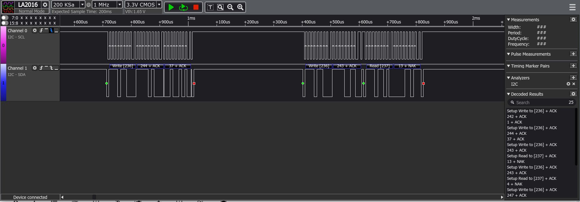
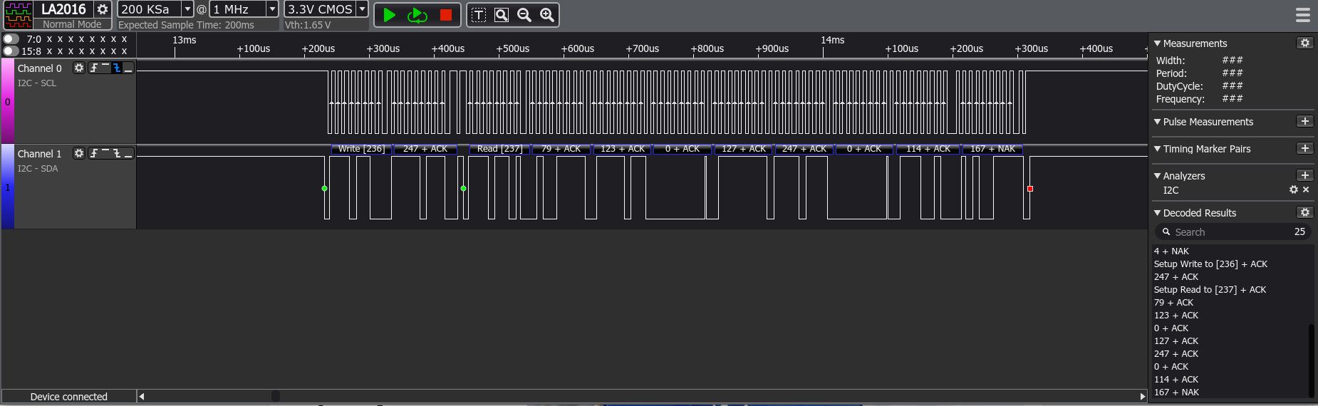
Edit: I added a longer dump of a i2c.readfrom_mem_into() call. You see again the write of a command followed by the read of 8 data bytes.
-
@robert-hh Thank you very much for your quick reply. (Whenever I look for information, I seem to come across one of your helpful posts. Amazing! Thank you so much!)
When I first looked at the CircuitPython code, I also thought it would not be too difficult to adopt. My interpretation of the buffer contents is different, though.
According to the datasheet (https://cdn-learn.adafruit.com/assets/assets/000/094/597/original/LC709203F-D.PDF?1599248750), battery monitor provides two methods, write_word and read_word. The CP code was written accordingly.
The first byte of the buffer does NOT seem to be the address. It is the code for the read_word or write_word operation. Hence the factor 2 in the code: address (0x0b) * 2 = write_word (0x16), address * 2 + 1 = read_word (0x17).
The second byte of the buffer is the command. I don't see any reference to an address in the slave's memory.
What follows is the word to or from the slave. The method for CRC calculation works fine.
There are certain parts of the CP code that I don't understand. It seems, e.g., that the first byte of the buffer is never transmitted.
Anyway, my battery monitor never responds. It is discovered by the scan, I can send messages to it, but I have not managed to get a reply. Could it be a protocol problem? The datasheet mentions "This LSI streches the clock", which has been discussed as a source of problems with Pycom devices a few years back. But to be honest, this is way beyond my understanding.
-
@toffee Looking at the adafruit code it should be pretty easy to adapt.
- init: Just expect a i2c object to be supplied, which is created before LC709023F is supplied.
- adapt the method _read_word() and _write_word(). Use i2c.readfrom_mem_into() instead of i2c.write_then_readinto(), and use i2c.writeto_mem() instead of i2c.write(). The buffer content has to be use to differently, since adafruit write the address into the first byte, where Pycom MP supplies it as call parameter. The memory address as second byte in the buffer is also supplied as parameter. The crc however is calculated over the whole data set.