Cannot access LoPy4 after connecting using UART, which has not enable
-
Hello,
I am using a LoPy4 and I connected using UART just to check if it was working. I had the LoPy in a breadboard just with the minimum circuit. I didn’t enable the UART before, and now the LoPy4 is not working, I am not sure if got blocked because of the UART access. Now when the LoPy4 is connected to visual studio code I get the following:
Connecting to /dev/tty.usbmodemPy56fb521...
ets Jun  8 2016 �ts Jun  88 00:22:57

rst:0x10 (ts_main.c �90
ets Jun  8 2016��*����ʘ$�ꕳ���崚��e�3 Jun  8 2016 00:22:57

rst:0xe�3 Jun  8 201600:22:57
rst:0x%x (%s),boot:0x%x (%s)
��*����ʘ$������ets Jun  8 2016 00:22:57

rst:0x1ets ���ets Jun  8 2016 00:22:57

rst:0xets Jun  8 2016 00:22:57

rst:0x10 (RRTCWDT_RTC_RESET),boot:0x33 (SPI_FAST_FLASH_BOOT)
configsip: ets Jun  8 2016 00:22:57

rst:0x10 (RTCWDT_RTC�ets Jun  8 2016 00:22:57

rst:0x10 (RTCWDT_RTC�RESET),boot:0�33 (SPI_Fets Jun  8 ets Ju��*����ʘ$�ꕳ���崚�e��!�ets Jun  8 201600:22:57
rst:0x%x (%��*�����ets Jun  8 2��*����ʘ$�ꕳ���崚�e��!�����������)5����������M��0�5������5т����*����ʘ$�ꕳ���崚�e��!�����������)5������������5U����*����ʘ$�ꕳ���崚�e�!������¸��������O¸���%����%龚������*����ʘ$�ꕳ���崚�e��!����������ets Jun  8 2016 00:22:57

rstt:0x10 (RTCWDT_RTC_RESET))boot:0x33 (SPI_FASet3 Jun  ��*����ʘ$��ets Jun  8 2016 �d

rst:0x10 (RTCWDT_RTC_RESET),boot:0x33 (SPI_FAST_FLASH_BOT)
��*����ʘ$�ꕳ���崚�e��!��������J-���ets Jun  8 2016 00:22:57

rst:0x10 (R�ts Jun  8 2016 00:22:57

rst:0x10 (RTCWDT_RTC_RESET),boot:0�33 (SPI_FAST_FLASH_BOOT)
ets ets Jun  8 2016 00:22:57ets Jun  8 2016 00:22:57

rst:0x10 (JTC��������������ets Jun  8 2016 00:22:57

rst:0x10 (RTCWDT_RTC_RESED),boot:0x33 (SPI_FAST_FLASH_BOOT)
c�.figsip: ets Jun  8 2016 00:22:57

rst:0x10 (RTCWDT_RTC_RESET),boot:0x33 (SPI_FAST_FLASH_BOOT)
co�ts Jun  8 2016 00:22:57
��*����ʘ$�ꕳ���崚��ets Jun  8 2016 00:22:57

rst:0x�0 (RTCWDT_RTC_RESETIllegalInstr��������ts Jun  8 2016 00:22:57

rst:0x10 (RTCWDT_RTC_RESET),boot:0x33 (SPI_FAST_FLASH_BOOT)
��*����ʘ$�ʟ#Q��������*����ʘ$�ꕳ���崚��*����ʘ$�ꕳ���崚��ets Jun  8 2016 00:22:57

rst:0x10 (RTCWDT_RTC�RESET),boot:0x33 (SPI_FAST_FLAH_BOOT)
ets Jun  8 2016 00:2��*��������������I���Ҙ$
                                           ��Ꚗҗ#Q��W¸�������oA�=
                                                                �������ʚ���������Ř��m]��핱����1-��������������#A��ets Jun  8 2016 %

r�t:0��*����ʘ$�e�3 J�.  8 201� 00:2�:�7�

r3�:08�0 (���T�TC_RESET),boot:0�3� (�I�ST�LASH��T)
�onfi�3ip� 0, SPIWP:0x�
clk_drv:0x00�1�$�6�0x0�,d_�r�:0x00,cs0_drv�0x�0,h�dr�:�800�7�d2v:0x�0�
�/de::DIO, clock �)v:1
�/ad:0x3fff8��*����ʘ$�ꕳ���崚�e���m��핱����1-�������ets Jun  8�2016��*����ʘ$�ꕳ���崚�e��!�����������)5��ts��*����ʘ$�ꕳ���崚�e��!��������ets Jun  8 2016 00:22:57

rst��*����ʘ$�ꕳ���崚�e��!�����������)5����ets

����3���*����ʘ$�ꕳ�����e��!��/��������15����������M����%�����5т��cէNq��J��
�.  8�2�1� 00���*����ʘ$�a���������ts Jun  8 2016 00:22:57

rst:0x10 (ets Jun  8 2016 00:22:57

rst:0x10 (RTCWDT_RTC_RESET),boote�33Jun  8 ets Jun  8 2016 00:22:57

rst:0x10 (RTCWDT_RTC_RESET),boot:0x33 (SPI_FAST�LASH_BOO)
c�nfigsip: 0, SPIWP:��*����3 Jun  8 2016 00:22:57

rst:0x10 (RTCWDT_RTC_RESET),boot:0x33K(ets Jun  8 2016 00:22�57
rst:0x%x (�s),boot:0ets Jun  8 2016 00:22:57

rst:0x10 (�TCWDT_RTC�RESET),boot:0ets Jun  8 2016 00:22:57

rst:0x10 (RTCWDT_RTC_RESET),boot:0x33 (SPI_Fets Jn  8 2016 00:22:57
I have try to update the firmware using the update firmware tool (Pycom Firmware Update). I have a expansion board 2, therefore, I connect P2 (G23) to GND to enable firmware update mode, but then I get the following message:
Failed to connect to ESP32: Timed out waiting for packet headerI have try also to download and upload the project in visual studio and I get the following error:
Uploading project (main folder)...
Not safe booting, disabled in settings
Uploading to /flash...
Upload failed.: timeout Please reboot your device manually.
So I try to reboot the device manually, by pushing the safe boot button in the expansion board. But I got no results. Also I connected P12 to 3.3v and got no orange led after 3 seconds, nothing.
Any ideas on how to get the LoPy working again?
thanks for all you help.
-
@Jorge-Romero So that's the configuration for COM4, which seems to be used with the LoPy4. If you say "without expansion board", you must have used another USB/UART converter.
-
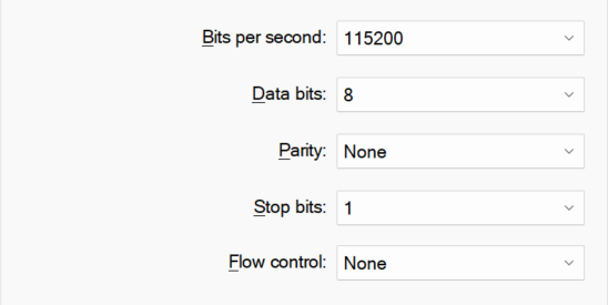
@robert-hh Hello, I have the baud rate setup in my PC's COM like this: 115200 baud, 8 bits, no parity
-
@Jorge-Romero That looks like a wrong baud rate. Is your PC's COM port set to 115200 baud, 8 bits, no parity?
-
Hi @elfarah, I would like to know if you had success with this problem. Currently I get the following output, connecting the LoPy4 without expansion board. Almost the same that you had been describing.
The LoPy4 port is found in the Atom IDE.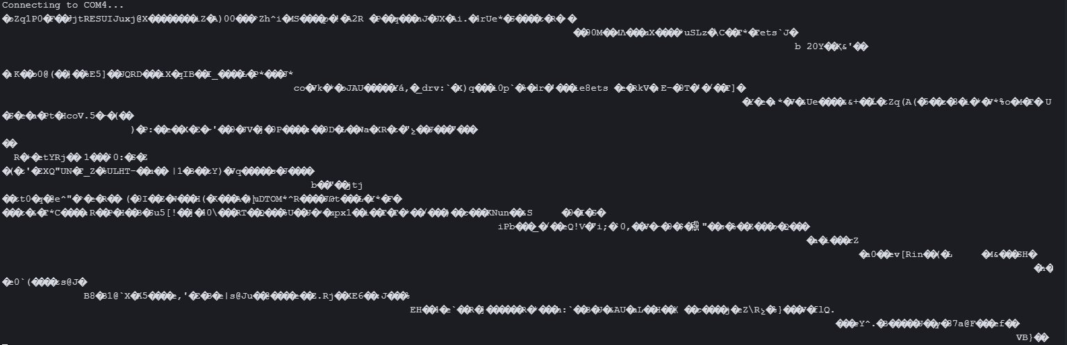
-
@elfarah That fuzz still looks like an hardware problem. Electrical connection, signal levels, crystal speed, .. and so on. If you have an oscilloscope, you could check that.
-
@Gijs Actually I had to downgrade the vscode to version 1.49 and pymakr to version 1.1.7 to make it work again.
Besides that, the problem that I got when connecting the LoPy4 with th expansion board 3.1 is the one describe above. I get the following output from the vscode terminal, when connected thru the expansion board:
e�3 Jun  8 2016 00�22:57

rst:0x�0 (RTCWDT_RTC�ESET),boot:ets ��*����ʘ$�ꕳ���崚�e���ets Jun  8 2016 00:2�:�7

rst:������ets ��*����ʘ$�ꕳ���崚�e��!������e�s Jun  8 2016 ets Jun  8�2016 ets Jun  8 2016 00:22:57

rst:0x�0 (RTCWDT_RTC�ESET),boot:0�3� (�I�ST�LASH_BOOT)
In the expansion board the leds are working. The LoPy4 port is found in the vscode. I checked Vin (equal to 4.96v) and the output 3.3v (is 3.4v in the back of the expansion board). Can it be other inputs of the LoPy4, that are not working and causing this restarts.
-
@elfarah said in Cannot access LoPy4 after connecting using UART, which has not enable:
I am not exactly sure why it is not working, and also I was not able to connect to the LoPy from vscode when using the usb-serial adapter, I am not sure if I need the expansion board to upload the code.
I know this is currently related to a bug in the latest VScode version of Pymakr where the serial connection does not work properly, we hope to have that fixed soon!
The LoPy4 when tested in three different expansion boards didn’t work. Others LoPy4s do work in all expansion boards tested.
I find it quite odd the one Lopy4 does not work in any of your expansionboard, while others do work. Could you elaborate some on that? (ie, no response on usb, not showing up in lsusb, leds status, possibly the voltages on Vin and 3V3 pins)
-
@robert-hh I didn’t have any success using the expansion board 3.1. When I connected P2 to GND and reset, I get no answer back from the LoPy4, in vscode terminal. So, I connected the LoPy4 to a breadboard, using a usb-serial adapter (the one that I thought cause the problem), and the minimum circuit, I was able to connect to the LoPy4. I then reset the device and got the message DOWNLOAD_BOOT, in a terminal. So, I opened the pycom firmware update software and updated the firmware of the LoPy and then, after reset, the code in main.py was running (as the LED changed colors indicating the code was running). So I put the LoPy back in the expansion board, open vscode, and got the same unrecognized characters and the
RTCWDT_RTC_RESETmessage. I disconnected the LoPy from the expansion board, connected another LoPy4 to same expansion board and it worked without any issues.As a summary:
-
I was able to update the firmware of the LoPy4 using a USB-serial adapter, a breadboard, and P2 connected to GND.
-
The LoPy4, in the breadboard and using the USB-serial adapter as power source is working.
-
The LoPy4 when tested in three different expansion boards didn’t work. Others LoPy4s do work in all expansion boards tested.
-
The LoPy4 in the breadboard works, the expansion board with other LoPys work, but the LoPy4 in any expansion board doesn’t work.
I am not exactly sure why it is not working, and also I was not able to connect to the LoPy from vscode when using the usb-serial adapter, I am not sure if I need the expansion board to upload the code.
Thanks for your help,
-
-
@elfarah P2 to GND + reset forces boot mode. This is implemented in the ESP32 boot ROM and cannot be bypassed. P2 of the LoPy4 module is GPIO0 of the ESP32.
If that connection is right,- try a different USB cable
- verify that you used the right USB port on your PC.
What do you see if you open the terminal window to the board, connect P2 to GND and push reset. You should see something like
rst:0x1 (POWERON_RESET),boot:0x3 (DOWNLOAD_BOOT(UART0/UART1/SDIO_REI_REO_V2))
waiting for download
-
@robert-hh I have try both the pycom-updater and the esptool.py, connecting P2 to GND, and pushing the reset button. The output is the same:
A fatal error occurred: Failed to connect to ESP32: Timed out waiting for packet headerAll jumpers are present in the expansion board.
-
@elfarah The pycom updater supports the expansion board 3.1 for switching into boot mode. Check that all jumpers on the board are present. esptool.py does not know how to tell the expansion board to go into boot mode.
In any case: Connecting P2 to GND and pushing reset will put the device into boot mode.
-
@robert-hh Hello I have a expansion board v3.1, the 2 was an old one and I was mistaken, sorry for that. How can I get the LoPy4, using the 3.1 expansion board, into boot mode? I have try P12 to 3.3v after reset, also using the safe boot button with no results. I also try the esptool and got the same error, timeout waiting for packet header.
-
@elfarah The expansion board 2 also does not support auto-switch to boot mode. To get into boot mode, you have to connect P2 to GND and push the reset button. Then you can start the updater.
-
@Gijs I have check the LoPy4 for broken pins, also the expansion board and everything looks ok. I have another expansion board with its USB cable (and another working LoPy4), so I have connect the not working LoPy4 there and I have the same results, so it looks like is not a problem with some broken pin (at least not in the expansion board or USB cable).
The firmware and the python code that was uploaded in the LoPy4 was working until I did the UART connection, by this I mean connecting the LoPy4 to a usb port using P0 and P1, and a USB Serial adapter.
Now the LoPy4 is connected to a expansion board 2, using a working USB cable. I try to update the firmware using the CLI firmware updater, but got the same result:Running in PIC mode Exception: Failed to connect to ESP32: Timed out waiting for packet headerCan it be that the LoPy4 has some pin broken "inside"? Should I run the erase_fs command? what else can I do?
Thanks for all your help
-
@elfarah That just looks like a bad connection.
- Try another USB cable.
- Check the connection between USB/UART adapter and LoPy4 including possibly used breadboards.
- Check that the USB/UART adapter is set to 3.3V I/O levels.
- Check that the LoPy4 is supplied with 5 V at the Vin pin. The 3.3v Output at common USB/UART boards cannot supply a LoPy4. The Current that can be delivered there is too low. Some adapters have a separate 5V output, which is just Vbus of USB.
-
@elfarah said in Cannot access LoPy4 after connecting using UART, which has not enable:
rst:0x10 (ts_main.c �90
(Just to clarify, with UART, you mean a USB-Serial adapter right? The expansionboard works very similar, except that it has additional functionality)
Extracting this from your first block, it might be the case there is a dodgy firmware on the device, or hints towards a dodgy connection. I've seen this text before, similar to this:rst:0x10 (RTCWDT_RTC_RESET),boot:0x33 (SPI_FAST_FLASH_BOOT) flash read err, 1000 ets_main.c 371Which might indicate some broken IO pins, or incorrect firmware. Could you check whether all headers on the expansionboard are in place?
Are you able to use the CLI firmware updater as described here: https://docs.pycom.io/advance/cli/ and erase the device, or does it give the same error?