some thoughts on the adc
-
Our early projects involved using the adc with a 4-20mA current loop sensor. Such a loop generates 400-2000mV across a 100 ohm resistor & fortunately the adc is vaguely linear over this range, although with an offset.
Recently we were wondering about trying some variations on our adc algorithm. The trouble with fiddling an adc read technique is that checking for improvements can be very time consuming. Best practice involves making 2 lists, readings Vs actual values, & comparing them which means you also need an accurate voltmeter. If you are OCD about this sort of thing you can even feed the lists into something like numpy poly fit & generate a polynomial to fit the readings list to the actual values.
What we needed was a way of automating the comparison. Our first idea was to feed the adc from the dac. Sadly the dac is worse than adc accuracy wise. The pwm does better except that the output for a duty cycle of 1 is about 13mv below the 3v3 rail voltage.
This program feeds the adc via a 10k resistor & a 1uF filter cap from the pwm & generates a lookup dictionary
import machine, time

pwm = machine.PWM(0, frequency=78000)
pwm_c = pwm.channel(0, pin='P11', duty_cycle=0)

adc=machine.ADC(); lkup={}; Vmax=3287

def _adc(ch):
  reads=300; set=[]
  for i in range(reads): count=adc.channel(pin=ch, attn=adc.ATTN_11DB); v=count.voltage(); set.append(v)
  set=sorted(set); median=set[reads//2]; mean=sum(set)//reads
  return median


print('   in millivolts'); print(' ADC PWM  DUTY  DIFF')
for duty in (0, .05, .06, .07, .08, .1, .3, .5, .7, .9, .95):
  pwm_c.duty_cycle(duty); time.sleep(.1); mv=_adc('P14'); val=int(Vmax*duty)
  diff=val-mv; print('%4d'%mv, '%4d'%val, '%.3f'%duty, '%3d'%diff); lkup[mv]=val
print(lkup)
from the results you can see the adc characteristic nicely.
    in millivolts
 ADC PWM  DUTY  DIFF
 142    0 0.000 -142
 193  164 0.050 -29
 225  197 0.060 -28
 254  230 0.070 -24
 287  262 0.080 -25
 354  328 0.100 -26
1007  986 0.300 -21
1671 1643 0.500 -28
2326 2300 0.700 -26
2954 2958 0.900   4
3108 3122 0.950  14
{1007: 986, 193: 164, 2954: 2958, 1671: 1643, 254: 230, 2326: 2300, 354: 328, 3108: 3122, 225: 197, 142: 0, 287: 262}
Next we copy the lookup dictionary into another program to try to trim the adc readings to more closely match the actual values
import machine, time

pwm = machine.PWM(0, frequency=78000)
pwm_c = pwm.channel(0, pin='P11', duty_cycle=0)

adc=machine.ADC(); steps=23; Vmax=3287
lkup={192: 164, 1007: 986, 2954: 2958, 1671: 1643, 254: 230, 2326: 2300, 354: 328, 3108: 3122, 225: 197, 142: 0, 287: 262}

def _adc(ch):
  reads=300; set=[]
  for i in range(reads): count=adc.channel(pin=ch, attn=adc.ATTN_11DB); v=count.voltage(); set.append(v)
  set=sorted(set); median=set[reads//2]; mean=sum(set)//reads
  return median

def _lookup (dic, KEY):
  lokey=min(dic, key=dic.get); hikey=max(dic, key=dic.get); lo=hi=9999
  if KEY<=lokey: return dic[lokey]
  if KEY>=hikey: return dic[hikey]
  for key in dic.keys():
    dif=key-KEY
    if dif>0:
      if dif<=hi: hi=dif; hikey=key
    elif dif<0:
      dif=abs(dif)
      if dif<=lo: lo=dif; lokey=key
    else: return dic[key]
  keydif=hikey-lokey; valdif=dic[hikey]-dic[lokey]
  a=dic[lokey]+valdif*lo/keydif; b=dic[hikey]-valdif*hi/keydif
  return int((a+b)/2)


print(' in millivolts'); print(' ADC PWM  DUTY  %DIFF')
for i in range(1,steps):
  duty=i/steps; pwm_c.duty_cycle(duty); time.sleep(.1); mv=_adc('P14'); mv=_lookup(lkup, mv); val=int(Vmax*duty)
  diff=100*(val-mv)/val; print('%4d'%mv, '%4d'%val, '%.3f'%duty, '%.1f'%abs(diff))
The output quickly shows changes in adc algorithms like changing the number of reads or using the mean instead of the median & takes some of the drudgery out of trying to squeeze the most from the adc.
 in millivolts
 ADC PWM  DUTY  %DIFF
 104  142 0.043 26.8
 282  285 0.087 1.1
 427  428 0.130 0.2
 568  571 0.174 0.5
 710  714 0.217 0.6
 856  857 0.261 0.1
1003 1000 0.304 0.3
1143 1143 0.348 0.0
1285 1286 0.391 0.1
1429 1429 0.435 0.0
1573 1572 0.478 0.1
1715 1714 0.522 0.1
1858 1857 0.565 0.1
1999 2000 0.609 0.1
2145 2143 0.652 0.1
2284 2286 0.696 0.1
2428 2429 0.739 0.0
2578 2572 0.783 0.2
2726 2715 0.826 0.4
2861 2858 0.870 0.1
3003 3001 0.913 0.1
3122 3144 0.957 0.7
-
For more resolution, there is the ADS1220, a 24 bits ADC using SPI, 4 channels, 2 ksamples/s, gain 1-128 :
https://www.ti.com/product/ADS1220
It is easy to buy break-out boards with ADS1220, e. g. :
https://www.aliexpress.com/premium/ads1220.html
https://www.tindie.com/products/whitchurch/ads1220-24-bit-4-channel-low-noise-breakout-board/
-
@JSmith If for speed, you can look at the ads7818 (12 bit, 500ks, single channel) or adc1015 (3300s, 12 bit, 2/4 channels). The limit is with all of these the transfer of data. But with the internal ADC you have besides linearisation to cope with the noise, which makes is effectively a 9 bit ADC.
-
After observing this issue myself I opted for an ADS1115 board as many other suggest (sourced from DFRobot). The trouble I found was that if wanting to use this in high speed mode, this can only be used with 1 of the 4 ADS inputs. If wanting >1 high res inputs then high speed mode cant be used and it thus becomes a slow device. - Maybe im missing something but that was my conclusion at the time.
Hence say if I wanted to implement closed loop control with fast and precise sampling this becomes expensive.
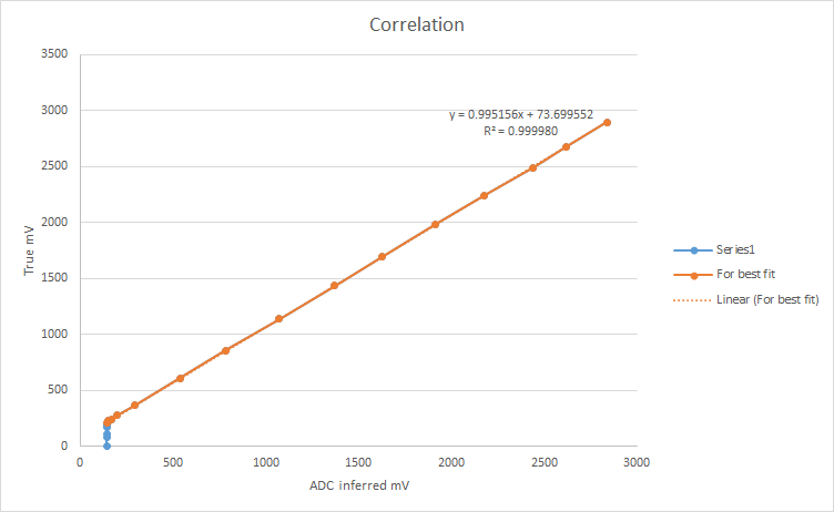
I agree that the ESP ADC is fine for many applications. And scaling errors can be accounted for, the main issue for me was the offset meaning the first 5% of the ADC range was immeasurable.
Below was the characterisation I measured:
-
@Gijs
I remember that link but the content was greatly expanded.
Really interesting, thx.
Especially interesting is that some chips are with ADC efused calibration and some without.
-
I wouldnt quite put it like that. The internal ADC should be fine for course measurements of a battery voltage and the like (personally I've been able to use it for quite a lot of things actually, from soil moisture sensors to piezo detectors and undersampled microphones). If you desire more precision / accuracy, I would indeed opt for the solution @rcolistete suggested.
There is some information about ESP32 ADC accuracy etc here: https://docs.espressif.com/projects/esp-idf/en/latest/esp32/api-reference/peripherals/adc.html, but Im guessing you've already been there.
-
True enough, there is only so much lipstick you can put on a pig.
-
What about using an ADS1015 (12 bits) or ADS1115 (16 bits) ADC ?
Both are I2C, easy to use and a lot better than the ESP32 ADC, which has many issues (noise, offset, non linearity) :
https://github.com/bboser/IoT49/blob/master/doc/analog_io.md