RGB backlight LCD 20x4 with WiPy
-
HI I have a 20x4 LCD display (https://www.adafruit.com/product/499). I was hoping to wire this up to one of my WiPy 3's. Are there any docs/examples that cover using one (or similar) the display ? Also, there is a Circuit Python library (https://github.com/adafruit/Adafruit_CircuitPython_CharLCD) so I'm hoping that will work with the WiPi.
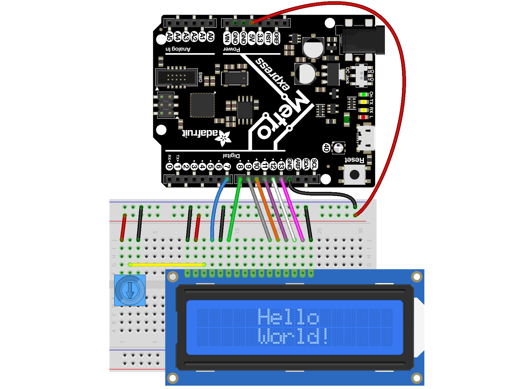
This is the pinout used by an Arduino
-
@cbourne Some convoluted history which has indeed confused many people. The origins are explained in the post I linked to above.
Note that IIRC you can use either the
Por theGnames when instantiating the pin. Personally I believe I've always used thePnames.
-
@robert-hh Thanks very much for your help that did the trick. However, I still don't understand why the pinouts are different between the Expansion Board and the WiPy board. Assume I should ignore the expansion board pinouts and just stick with the WiPy even though its installed in the expansion board.
-
@cbourne see https://github.com/pycom/pycom-micropython-sigfox/blob/Dev/esp32/boards/WIPY/pins.csv for the mapping between the different pin naming conventions for the WiPy and https://forum.pycom.io/topic/3919/mapping-of-g-pins-and-p-pin-on-exp-board-v3/10 for an explanation of the origin of the various numberings.
-
@cbourne Assuming that with Pin(4) etc. you want to address the P4 pin, you have to write:
rs_pin=Pin("P4")
and so on for the other pins.. See https://docs.pycom.io/tutorials/basic/gpio/ or https://docs.pycom.io/firmwareapi/pycom/machine/pin/.
-
OK so I tried this based on re-wiring the display to use the pins defined in the
test_mainfunction:# main.py -- put your code here! """Implements a HD44780 character LCD connected via ESP32 GPIO pins.""" from machine import Pin from esp32_gpio_lcd import GpioLcd from utime import sleep_ms, ticks_ms # Wiring used for this example: # # 1 - Vss (aka Ground) - Connect to one of the ground pins on you pyboard. # 2 - VDD - I connected to VIN which is 5 volts when your pyboard is powered via USB # 3 - VE (Contrast voltage) - I'll discuss this below # 4 - RS (Register Select) connect to G4 (as per call to GpioLcd) # 5 - RW (Read/Write) - connect to ground # 6 - EN (Enable) connect to G11 (as per call to GpioLcd) # 7 - D0 - leave unconnected # 8 - D1 - leave unconnected # 9 - D2 - leave unconnected # 10 - D3 - leave unconnected # 11 - D4 - connect to G5 (as per call to GpioLcd) # 12 - D5 - connect to G18 (as per call to GpioLcd) # 13 - D6 - connect to G21 (as per call to GpioLcd) # 14 - D7 - connect to G22 (as per call to GpioLcd) # 15 - A (BackLight Anode) - Connect to VIN # 16 - K (Backlight Cathode) - Connect to Ground # # On 14-pin LCDs, there is no backlight, so pins 15 & 16 don't exist. # # The Contrast line (pin 3) typically connects to the center tap of a # 10K potentiometer, and the other 2 legs of the 10K potentiometer are # connected to pins 1 and 2 (Ground and VDD) # # The wiring diagram on the following page shows a typical "base" wiring: # http://www.instructables.com/id/How-to-drive-a-character-LCD-displays-using-DIP-sw/step2/HD44780-pinout/ # Add to that the EN, RS, and D4-D7 lines. def test_main(): """Test function for verifying basic functionality.""" print("Running test_main") lcd = GpioLcd(rs_pin=Pin(4), enable_pin=Pin(5), d4_pin=Pin(6), d5_pin=Pin(7), d6_pin=Pin(8), d7_pin=Pin(9), num_lines=4, num_columns=20) lcd.putstr("It Works!\nSecond Line\nThird Line\nFourth Line") sleep_ms(3000) lcd.clear() count = 0 while True: lcd.move_to(0, 0) lcd.putstr("%7d" % (ticks_ms() // 1000)) sleep_ms(1000) count += 1 test_main()However, it now just throws the following error:
Running test_main
Traceback (most recent call last):
  File "<stdin>", line 1, in <module>
  File "<stdin>", line 41, in test_main
ValueError: invalid argument(s) value
-
@cbourne You just have to declare the pin objects with the names used with a pycom device. So instead of 11 on a MP ESP32, it would be something like "P4". You are free in selecting any Pin for the LCD that can be used for output. That means, do NOT use P13 though P18 on a WiPy device, because these are input only.
-
Thanks for the response. Well, think its time to go with another board. I have a WiPy installed in an expansion 3.1 board and the pinouts make no sense. They are completely different from the pinouts for the WiPy. e.g. The expansion board pinouts show there is a GPIO11 but according to pinouts for the WiPy there is no 11.
-
@cbourne Dave Hylands has made a nice set of LCD drivers. You'll find the here: https://github.com/dhylands/python_lcd.git.
They are made for the genuine MicroPython, but are easy adaptable. my first choice would be esp32_gpio_lcd.py. Please bear in mind, that the LCD runs at 5V. As long as you only connect LCD inputs, that is not an issue. You need to set the contrast. That's what the pontentiometer is for on your picture. Also, your picture does not match the device. The picture shows 16 pins, the device has 18. The two additional ones are on the left for the additional LED colors.