LoPy4 - I2C - FRAM Memory - MicroPython Library
-
Hi!,
I am working on a project where I am building an industrial lubrication system controller, my application requires me to have a way to save user-selected parameters for the controller to access and config on boot. I got a custom-made shield for my project that takes a LoPy4 as a controller.
my shield is equipped with a FRAM - MB85RC256VPF-G-JNERE2 chip SDA->P9, SCL->P10, and Write Protect on P2.
It's my first project with MicroPython and Pycom. I managed to have all my other functionalities figured out from the documentation except my FRAM.
I am having problems finding a library or information to help me achieve my results. at this point, I think I may need to write my own firmware which is way above my abilities for now.So far in my research, I found a discussion and a link to PeterHinch's Github repo that brings me to a dead end. I was looking at is GitHub projects and i did not see anything referring to FRAM I2C but he has is lots of other amazing work I am glad I found. I think it may have been deleted overtime.
I also found a Repo from Adafruit but it is for circuit python. https://github.com/adafruit/Adafruit_CircuitPython_FRAM.I am wondering if anyone knows about or has seen something that could help me out.
Thanks
Eric
-
@Eric-Tremblay Ah sorry I had missed that.
No, the message is correct. The address is on 16 bits, so takes two bytes to send.
What happens when you try a read?
-
@jcaron i had it posted in June its in the thread bellow
-
@Eric-Tremblay could you share what you see?
-
@jcaron i got a logic analyzer to help me with this issue.
it looks like i'm getting an extra byte of 0x00 in there.
what do you think?
-
Hello everyone who was helping me diagnose this issue. I finally got my logic analyzer.
See if something looks odd in the serial data
here is an example of a I2C capture
code:
i2c.writeto_mem(0x51,0x3,4,addrsize=16)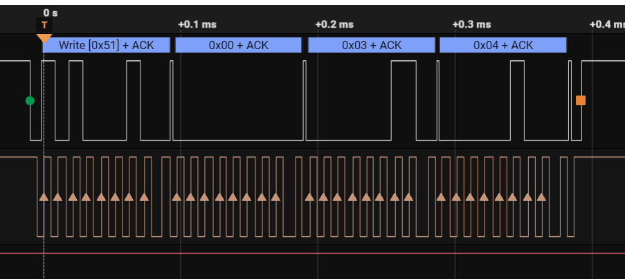
-
@jcaron I just double-checked to make sure and I read the schematic wrong they are indeed 10k, SMD 1002.
-
@jcaron , They are SMD resistors on a custom PCB. I'm not equipped to change them. I will talk with the engineer that designed my board and see if he can make the change he has a few boards incomplete (missing chips) as we are just starting to test them.
-
@Eric-Tremblay 100K may be too weak (i.e. the numerical value is too high) for the pull-up. Can you easily change those to a different value? Usual recommandations are 4.7K or 10K, though some use much lower values.
It seems weird that the scan still works if that is indeed the problem, but it might be an edge case due to rise/fall times.
You may also want to try different speeds to see if that changes anything. Lower speeds are less sensitive to pull-up issues.
-
Base i2c gives me and TypeError when I pass in a byte array
>>> i2c.writeto(0x51, 2,)
1
>>> i2c.readfrom(0x51, 5)
b'\x00\x00\x00\x00\x00'
>>> i2c.writeto(0x51, bytes(0,0,1,2,3,4))
Traceback (most recent call last):
  File "<stdin>", line 1, in <module>
TypeError: wrong number of arguments
>>>
This returns the entire memory all zero
>>> i2c.readfrom_mem(0x51,0x0,32768,addrsize=16)
b'\x00\x00\x00\x00\x00\x00\x00\x00\x00\x00\x00\x00\........   Returns all memory
-
@Elizar There are low cost logic analyzers available for about 10€, with 8 channels at 24MHz max sampling rate. Software is available as supporting the most common serial protocols. For I2C, UART, SPI that is extremely valuable. It does not help you though when there are analogue problems like with voltage levels.
-
@Elizar interesting idea! You probably want to use a camera to record that, though, it’ll make transcription easier.
-
@Eric-Tremblay Since the I²C bus can be clocked very slow, say 1 Hz (1 clk pulse per second), you may not need a scope. You can use two simple LEDs (each in series with a resistor of about 5 kohm. The LEDs will be a bit dark but not load the bus too much). Connect the LEDs from SDA via resistor to GND and do the same for SCL.
Then you can follow the signals on the I²C bus and see what happens. Pay special attention to the final bit of each transmitted byte (the acknowledge bit). Then compare the results with the waveforms from the datasheet.
Nevertheless, a scope with at least two channels would make the observation much, much simpler. If you can afford it, buy it. It will save you many painful hours of guessing.
-
@Eric-Tremblay you may want to try the “base” I2C commands instead of the memory commands, there may be something slightly different in the implementation which isn’t immediately apparent and wouldn’t be compatible with the *mem functions.
Use:
i2c.writeto(0x51, bytes(0,0,1,2,3,4))This should write bytes 1,2,3,4 at addresses 0,1,2,3.
Then:
i2c.writeto(0x51, bytes(0,0))This should reset the pointer to address 0
Then:
i2c.readfrom(0x51, 4)To read back the data.
The result of the full read would be interesting as well.
-
Sorry typo i meant 3.3
-
@jcaron i dont have a scope but i think i may need one to help me troubleshoot this out. Will see if i can buy one. There is 13.3 on the VDD
-
@Eric-Tremblay can you check if VDD is 3.3V as well? Can you capture an exchange with a scope or other tool?
Just for reference, can you run:
i2c.readfrom_mem(0x51,0x0,32768,addrsize=16)That should read the whole memory. It would be interesting to see if there’s something other than zeroes in the output.
-
There is 100k pull up on both SDA and SCL I checked voltage on wp and i get 3.3vdc when H and 0 when L
-
@Eric-Tremblay do you have pull ups on SCL and SDA? Is the chip powered at 3.3V (rather than 5V)?
Do you have a scope you could use to capture SCL and SDA? Have you checked actual voltage on WP?
-
Just check my WP pin status to make sure it was "L"
>>> wp = Pin("P2", mode = Pin.OUT)
>>>
>>> wp()
0
>>> i2c.writeto_mem(0x51,0x2,bytearray(0x42),addrsize=16)
66
>>> i2c.readfrom_mem(0x51,0x2,1,addrsize=16)
b'\x00'
>>>