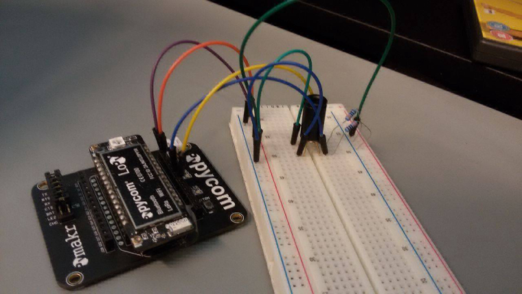
Using MLX90614 temperature sensor
-
I have been trying to get the temperature reading using I2C protocol. Whenever I run the code it keeps giving me the error IndexError: list index out of range. What are the SDA and SCL pins on LoPy? Could anyone give me a suggestion how to go about it?

-
I have been working on the mlx90614 for the last day and can communicate successfully with 6 on an I2C bus, but am am receiving an overwhelming number of errors. Right now it hovers around 25% of attempts to read the sensor. I believe it could be related to a timing issue of the I2C communication in micropython.
Some errors are the result of a bad read of the I2C data, which can be verified if you read the PEC byte after the data. The third byte should come back with a crc-8 value, but sometimes it comes back as 0xFF, as if the mlx90614 is one byte ahead of the lopy.
The other error is related to readfrom_mem function in i2c. This error produces an OSError exception about every one in four attempts. In other mlx90614 libraries the flow for reading bytes is slightly more complicated, for example
// send the slave address then the command and set any
// error status bits returned by the write
Wire.beginTransmission(_addr);
Wire.write(cmd);
_rwError |= (1 << Wire.endTransmission(false)) >> 1;

// experimentally determined delay to prevent read errors
// (manufacturer's data sheet has left something out)
delayMicroseconds(30);

// resend slave address then get the 3 returned bytes
Wire.requestFrom(_addr, (uint8_t)3);

// data is returned as 2 bytes little endian
val = Wire.read();
val |= Wire.read() << 8;

// read the PEC (CRC-8 of all bytes)
_pec = Wire.read();

return val;
Is there anyway to imitate this flow control? Using the above style code on an Arduino I receive no errors and do not have to do coding gymnastics to control errors.
-
@timeb said in Using MLX90614 temperature sensor:
MLX90614
https://github.com/mcauser/micropython-mlx90614/blob/master/mlx90614.py
-
@jmarcelino Is there a library for MLX90614 sensors that I can use?
-
@jmarcelino I will look into it. Thanks.
-
@timeb
Do you have a logic analyser or oscilloscope?I wonder if the MLX device is in PWM mode.
I'm not exactly sure how to change it but the datasheet suggests holding the SCL line low for longer than 1.44ms before initiating I2C.
-
@jmarcelino I changed that but I still get [8, 9, 10, 11, 12, 13, 14, 15, 16, 17, 18, 19, 20, 21, 22, 23, 24, 25, 26, 27, 28, 29, 30, 31, 32, 33, 34, 35, 36, 37, 38, 39, 40, 41, 42, 43, 44, 45, 46, 47, 48, 49, 50, 51, 52, 53, 54, 55, 56, 57, 58, 59, 60, 61, 62, 63, 64, 65, 66, 67, 68, 69, 70, 71, 72, 73, 74, 75, 76, 77, 78, 79, 80, 81, 82, 83, 84, 85, 86, 87, 88, 89, 90, 91, 92, 93, 94, 95, 96, 97, 98, 99, 100, 101, 102, 103, 104, 105, 106, 107, 108, 109, 110, 111, 112, 113, 114, 115, 116, 117, 118, 119]
-
@timeb
I may be misunderstanding your photo but aren't the signal pins swapped? SDA going to G6 and SCL to G7?If so change the I2C(pins=.(..)) init accordingly.
-
@livius I removed the resistors. I don't get what seems to be the problem?
-
@timeb
For me it looks strange you should see only 5A(90)did you removed this resistors?
-
@jmarcelino So then I get this when I used i2c.scan(). Does it mean it is working?
[8, 9, 10, 11, 12, 13, 14, 15, 16, 17, 18, 19, 20, 21, 22, 23, 24, 25, 26, 27, 28, 29, 30, 31, 32, 33, 34, 35, 36, 37, 38, 39, 40, 41, 42, 43, 44, 45, 46, 47, 48, 49, 50, 51, 52, 53, 54, 55, 56, 57, 58, 59, 60, 61, 62, 63, 64, 65, 66, 67, 68, 69, 70, 71, 72, 73, 74, 75, 76, 77, 78, 79, 80, 81, 82, 83, 84, 85, 86, 87, 88, 89, 90, 91, 92, 93, 94, 95, 96, 97, 98, 99, 100, 101, 102, 103, 104, 105, 106, 107, 108, 109, 110, 111, 112, 113, 114, 115, 116, 117, 118, 119]
-
I connected the two pull-up resistors to the SDA and SCL
Do you mean pull down? I see it on picture (if i see ok)
But as @jmarcelino say you shouldn't need the pull-up resistors
-
@timeb
Thanks, so if your SDA is G7 and your SCL is G6 you should setup I2C as:i2c = I2C(0, I2C.MASTER, baudrate=100000, pins=('G7', 'G6'))
or
i2c = I2C(0, I2C.MASTER, baudrate=100000, pins=('P20', 'P19'))if like me you prefer the Px syntax
You shouldn't need the pull-up resistors, I2C on the LoPy turns on the internal pull-ups which should work for most situations.
-
@timeb I connected the two pull-up resistors to the SDA and SCL of the MLX90614. Then SDA and SCL from MLX90614 go to G7 and G6 pin of the LoPy respectively. I connect Ground of MlX90614 to Ground on LoPy and power to 3.3v on LoPy.
-
@timeb
I'm afraid that photo isn't very helpful, can you list which pins go where?
-
-
@timeb
Ok BCF sounds good (don't know about the rest of that ID)How have you connected to the LoPy and power?
-
@jmarcelino It is BCF2241B20
-
@timeb
Which MLX90614 are you using? The 5 volt version (MLX90614Axx ) is probably difficult to interface with the LoPy.
-
@timeb
you decide where you connect i2c
default are (https://docs.pycom.io/pycom_esp32/pycom_esp32/datasheets.html):P9 (SDA) and P10 (SCL)but you can tell where you connect it like:
i2c = I2C(0, I2C.MASTER, baudrate=100000, pins=('P19', 'P20'))
