I2C Pullup Resistors
-
I've seen several posts that talk about I2C pullup resistors, and I want to be sure I understand what is actually happening. My interpretation is that the pullups are internally enabled on I2C, but only if you use the default pins of P9/P10 (and in that case, no external I2C pullups are needed). Is that correct? If so, why should it matter what pins are used, so long as the pins are normal I/O pins that support the internal pullup?
-
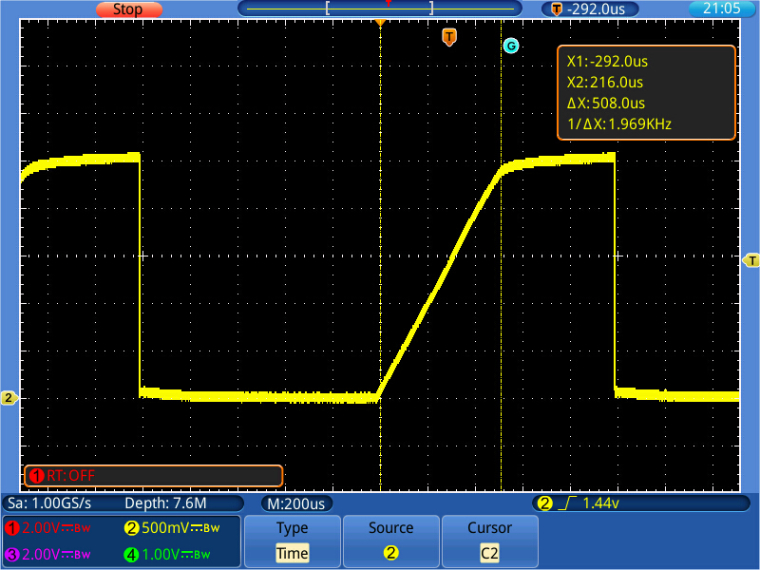
@Eric24 For what it's worth, I repeated the test with a 10nF capacitor and a test code, which switches the output value high/low. To my surprise, the figure looks as if the capacitor is charged with a constant current. The calculation gave a current of ~47 µA, which matches the 1.53V seen across the 33k resistor.
-
@robert-hh Thanks for the effort!
@bucknall Alex: I've searched high and low for an answer to this (on the ESP32 as well) and it doesn't appear to be documented anywhere. This would be a really good think to know and not have to guess or experiment to find out.
-
@Eric24 No. I made a quick static measurement, using a 33k resistor as load, and that indicated an internal pull-up of 22k. The confusing thing was, that the open port high output value was 2.56 V, when I expected 3.3 V. If I do my calculation against that 3.3 V, the result would be 38k for the internal pull-up. The other option would be to use an external capacitor as load and look at the time constant of the rising slope.
-
@robert-hh Do you happen to know the value of the internal pull-up resistors?
-
@mike632t The internal pull-up resistors are a 'weak pull-up', meaning that they are good for a single device, short connections and moderate speed. If you face a situation, that the device works at low speed, bit not at high speed, add external pull-up resistors. The typical value is 4.7 kOhm. You need just one pair of resistors for the whole bus. If you use one of the convenient pre-assembled modules for sensors and other peripherals, check if they do not have already pull-up resistors populated. Often they have, for the convenience of the user. Then you might run into the opposite problem. If you connect too many of these modules, the total pull-up value may get too low.
-
I don't mean to add more confusion but when experimenting with the I2C bus a couple of weeks ago I found that the internal pull up did NOT appear to be enabled when using pins other then P9 and P10.
See this post.
Are there differences in the way this is handled in different versions of the firmware?
-
@Eric24 @jmarcelino just seen this, logged it on my docs todo list! Thanks for handling this Jose :)
-
@jmarcelino Perfect. That was my assumption, but I wanted to be sure, in light of all the confusion over this in other forum posts.
PS - This would be a good detail to include in the documentation.
-
@Eric24
The pins are set to open drain, pull up automatically on calling I2C init:pin_config (self->scl, -1, -1, GPIO_MODE_INPUT_OUTPUT_OD, MACHPIN_PULL_UP, 1); pin_config (self->sda, -1, -1, GPIO_MODE_INPUT_OUTPUT_OD, MACHPIN_PULL_UP, 1);https://github.com/pycom/pycom-micropython-sigfox/blob/master/esp32/mods/machine_i2c.c#L135
-
@jmarcelino OK (and understood about the input-only pins). Are the pullups automatically enabled by the I2C driver or must this be done manually?
-
@Eric24
Any free pin will work and will enable the internal (weak) pull-up except for P13, P14, ... to P18 which are input only as shown in the pinout diagram.