LoPy pinout (work in progress)
-
It's late and I might be wrong but I think UART1 should be P3 RX1 and P4 TX1.
-
@Xykon Hmmm.... I can double check what I did tomorrow. But also remember that Tx on peripheral device goes to Rx on master, and vice-versa for the other combo. They need to criss-cross so that one is transmitting to another's receiving pin. A little confusing, I know.
-
I connected an FTDI breakout board to UART1 and wired TX on the FTDI to P3 and RX to P4. I disconnected it for the night will check again tomorrow.
-
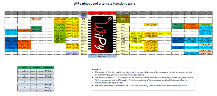
i suppose that this should be compatibile with wipy yes or no?
-
@livius said in LoPy pinout (work in progress):
i suppose that this should be compatibile with wipy yes or no
That is for wipy 1.0 not wipy 2.0
-
@littlebat said in LoPy pinout (work in progress):
i suppose that this should be compatibile with wipy yes or no
No as they use different chips (cc3200 in the WiPy1 and ESP32 in the LoPy / WiPy2).
For example WiPy1 doesn't have JTAG on the expansion header while the LoPy does.
-
I've uploaded the Excel file I used to make the image in case anyone wants to make modifications.
-
You may want to take a look at the ESP32 technical reference manual. Section 4.10 IO_mux and 4.11 RTC_mux list the dedicated alternate functions for each pin, but more importantly, section 4.9 GPIO matrix lists all the functions that can be mapped anywhere, which includes those UART and I2C functions (there are over a hundred each direction). In short, unless the software does something silly, there's no particular pin for RX1/TX1 et cetera (micropython should use the GPIO matrix). UART 0 only has them because the bootloader ROM selects those pins, though I'm not certain if it does it via the IO mux or GPIO matrix.
-
Yes I'm aware of that... I was just putting in the defaults for SPI0, I2C0 and UART0/1 as the examples in the quick reference do not specify any custom pins.
-
I see. It's the default arguments of the micropython port we're looking for then. The chosen pins don't match the IO mux. A comment in https://docs.pycom.io/lopy/lopy/quickref.html#pins-and-gpio seems to be the documentation we get.
UART 1 pins are most likely chosen to match the WiPy 1.0 (CC3200) layout documented in https://docs.pycom.io/wipy/wipy/quickref.html but the I2C looks different. Hopefully we can clean the documentation up once the project opens up a bit.
-
@Xykon OK, so I again verified my results.
Connecting a slaves RX pin to P3 and the slaves TX pin to P4 yielded results. I tried it the other way, and nothing.So again, I stand behind what I stated before.
Slaves RX ---> LoPy Tx - P3
Slaves Tx ---> LoPy Rx - P4The criss-cross is confusing I know, but this is the standard way of wiring UART and naming the pins. The slave I am using is well labeled, and I have tested the same exact wiring scheme named above using other microcontrollers. I am now pretty positive of those two pins.
-
@mfgeorge It looks like the DFRobot FTDI breakout board I was using to test UART1 has RXI and TXD inverted. I compared it to the Sparkfun FTDI breakout I was using for UART0 and it has the RXI and TXD the other way around.
Lesson learned: Never trust the silkscreen on cheap breakout boards. I will update the graphic tomorrow.
-
-
@pighixxx Thanks! I'd like some small additions if possible.
- Which level to use to select internal antenna
- Bootstrapping pins:
2a. P2 for the low level bootloader, must not be grounded for normal bootup
2b. P12 for the multiboot / safemode, which should not be kept high for normal MicroPython use
I haven't dug around for the capacitive touch features, but I'd have expected that SensVN and SensVP formed one pair, and SensCN and SensCP would form another. Still much to learn.
-
Hi,
Today i release the WiPy and Pymakr pinouts then I make the changes to WyPy pinout in the next revision.
-
@pighixxx I guess you mean Pymakr = LoPy?
-
Is the Expansion Board
-
This is the revised version:

-
nice but all pins are PWM?
-
@livius said in LoPy pinout (work in progress):
nice but all pins are PWM?
I'd rather say all pins can be assigned to one of the 8 high or low speed PWMs.

Hello! It looks like you're interested in this conversation, but you don't have an account yet.
Getting fed up of having to scroll through the same posts each visit? When you register for an account, you'll always come back to exactly where you were before, and choose to be notified of new replies (either via email, or push notification). You'll also be able to save bookmarks and upvote posts to show your appreciation to other community members.
With your input, this post could be even better 💗
Register Login