LoPy pinout (work in progress)
-
@Xykon OK, so I again verified my results.
Connecting a slaves RX pin to P3 and the slaves TX pin to P4 yielded results. I tried it the other way, and nothing.So again, I stand behind what I stated before.
Slaves RX ---> LoPy Tx - P3
Slaves Tx ---> LoPy Rx - P4The criss-cross is confusing I know, but this is the standard way of wiring UART and naming the pins. The slave I am using is well labeled, and I have tested the same exact wiring scheme named above using other microcontrollers. I am now pretty positive of those two pins.
-
I see. It's the default arguments of the micropython port we're looking for then. The chosen pins don't match the IO mux. A comment in https://docs.pycom.io/lopy/lopy/quickref.html#pins-and-gpio seems to be the documentation we get.
UART 1 pins are most likely chosen to match the WiPy 1.0 (CC3200) layout documented in https://docs.pycom.io/wipy/wipy/quickref.html but the I2C looks different. Hopefully we can clean the documentation up once the project opens up a bit.
-
Yes I'm aware of that... I was just putting in the defaults for SPI0, I2C0 and UART0/1 as the examples in the quick reference do not specify any custom pins.
-
You may want to take a look at the ESP32 technical reference manual. Section 4.10 IO_mux and 4.11 RTC_mux list the dedicated alternate functions for each pin, but more importantly, section 4.9 GPIO matrix lists all the functions that can be mapped anywhere, which includes those UART and I2C functions (there are over a hundred each direction). In short, unless the software does something silly, there's no particular pin for RX1/TX1 et cetera (micropython should use the GPIO matrix). UART 0 only has them because the bootloader ROM selects those pins, though I'm not certain if it does it via the IO mux or GPIO matrix.
-
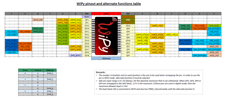
I've uploaded the Excel file I used to make the image in case anyone wants to make modifications.
-
@littlebat said in LoPy pinout (work in progress):
i suppose that this should be compatibile with wipy yes or no
No as they use different chips (cc3200 in the WiPy1 and ESP32 in the LoPy / WiPy2).
For example WiPy1 doesn't have JTAG on the expansion header while the LoPy does.
-
@livius said in LoPy pinout (work in progress):
i suppose that this should be compatibile with wipy yes or no
That is for wipy 1.0 not wipy 2.0
-
i suppose that this should be compatibile with wipy yes or no?
-
I connected an FTDI breakout board to UART1 and wired TX on the FTDI to P3 and RX to P4. I disconnected it for the night will check again tomorrow.
-
@Xykon Hmmm.... I can double check what I did tomorrow. But also remember that Tx on peripheral device goes to Rx on master, and vice-versa for the other combo. They need to criss-cross so that one is transmitting to another's receiving pin. A little confusing, I know.
-
It's late and I might be wrong but I think UART1 should be P3 RX1 and P4 TX1.
-
@mfgeorge Updated image with additional information provided.
-
No Problem...
Another live update. For UART Bus 1 (ie. uart = UART(1,baudrate=9600)) the pins are:
P3 - UART TX Bus 1
P4 - UART RX Bus 1
-
Thanks... it looks like you've done the same thing I did tonight. Currently doing some tests with a simple 24LC64 eeprom.
-
Hello all,
I have found the i2c pins for bus 0 (currently the only one that does not throw an OSError during instantiation).
P9 - SDA Bus 0
P10- SCL Bus 0Again this is presumably for i2c bus 0. ie i2c_object = I2C(0, I2C.MASTER)
Method for finding these pins:
These pins were found by looping a "while True: i2c.scan()" in the REPL prompt and scoping around for a clock signal. After the clock signal was found I continued the i2c.scan() and plugged in an i2c sensors SCL to the P10, and checked to either side with the sensors SDA pin and found the address for the sensor was reported back while SDA was connected on P9.
Hope this helps and happy hacking everyone!
-
@LoneTech said in LoPy pinout (work in progress):
Here's a little surprise: GPIO 34 and up don't have output capability, according to the technical reference manual. That's P13 to P18 on the LoPy. Initial experiments seem to support this; I'm not getting them to output anything. This is because they have dedicated analog input functions, apparently. Perhaps this is why they are blank in your table?
Sorry took me a while to see your latest update. I will update my image with your findings tomorrow.
I first started using the blink example from esp-idf to find the JTAG pins using a logic analyser to see which pin would change states. I then used openocd-esp32 to write to GPIO_OUT_REG and GPIO_OUT1_REG to try and identify the rest of the pins.
Since P13-18 are input pins (a fact that I missed in the reference manual) it makes sense that I couldn't identify them.
-
I can map them out using the GPIO registers (low level access can be useful sometimes).
import machine, esp32  # esp32.py from github
def findpin(name):
    pin=machine.Pin(name)
    irq=pin.irq(trigger=pin.IRQ_RISING,
                handler=lambda p: None)
    candidates=[i for i in range(40)
                if esp32.GPIO.pin[i].int_type]
    pin.irq(trigger=0).disable()
    return name, candidates
For some reason, running it in a loop doesn't work properly, but here's the result:
('P0', [3])
('P1', [1])
('P2', [0])
('P3', [4])
('P4', [15])
('P5', [5])
('P6', [27])
('P7', [19])
('P8', [2])
('P9', [12])
('P10', [13])
('P11', [22])
('P12', [21])
('P13', [5])
('P14', [4])
# 15 and 16 caused hangs
('P17', [3])  # maybe 35?
('P18', [2])  # maybe 34?
('P19', [0])  # 32?
('P20', [1])  # 33?
('P21', [26])
('P22', [25])
('P23', [14])
I suspect the low numbers for P13-P20 is a firmware bug related to GPIO>32.
The quick reference indicates that LoRa is connected on P5-P7 (using SPI) and the RGB LED is on P2.
The expansion board connects P0=RX0, P1=TX0, P4=SD-CMD, P8=SD-DAT0, P9=LED, P10=button, P16=Vbat, P19=CTS, P20=RTS, P23=SD-CLK.
I kind of hope that JTAG port is disabled, or it might do funny things when the button gets pressed.
Perhaps my next step is finding the LoRa SPI pinout.
Also, considering the WiPy 1.0 had ADC pins on G5, G4 and G3 (P13, P14 and P16) we can expect those are RTC pins on the LoRa. That would be GPIO 0,2,4,12-15,25-27,32-39.
Tracking down the LoRa SPI:
>>> GPIO.func_out_sel_cfg[5].func
63
>>> GPIO.func_out_sel_cfg[27].func
65
>>> GPIO.func_out_sel_cfg[19].func
256
>>> GPIO.func_in_sel_cfg[64].gpio
19
Output 63 is VSPICLK_out_mux. Output 65 is VSPID_out. 256 is GPIO, but just means that pin isn't used for output. Input 64 is VSPIQ_in. Looks like the VSPI is used to talk to the LoRa radio.
Some careful probing suggests that P15 is GPIO 32+6=38, and P16 is GPIO 39. I don't know why they cause so much trouble; merely calling
Pin('P15')causes a crash, butPin.module.P15exists. Some operations on it don't work. Similar probing shows P13=37, P14=36, P15=38, P16=39, P17=35, P18=34, P19=32, P20=33.Here's a little surprise: GPIO 34 and up don't have output capability, according to the technical reference manual. That's P13 to P18 on the LoPy. Initial experiments seem to support this; I'm not getting them to output anything. This is because they have dedicated analog input functions, apparently. Perhaps this is why they are blank in your table?