Protection circuit for Analog Pin
-
Hi,
I am trying to create a protection and range adjustment circuit for the Analog input that I am getting from the field.
I need to change the range from -3V to +3V to 0V to +3V which I achieve by supplying 3.3V from the FiPy and a voltage divider.
Then I have a Schottky and Zener diode to protect from high positive and negative voltage.
I can achieve this using the circuit below.
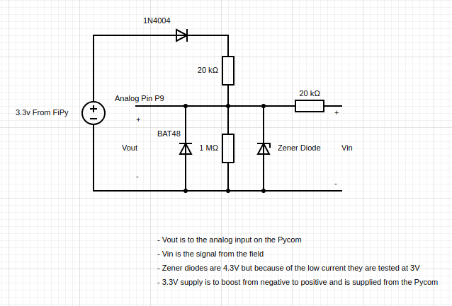
However, my problem is that the FiPy spends most of its time is deep sleep and when that happens the FiPy shuts down and I was worried that the 3.3 V pin would get a negative voltage. So I put a diode to stop that but it can still get up to -0.1V on the 3.3V output pin. I am assuming this will cause a problem for the FiPy?
I considered getting the supply direct from the 3.7V battery but when there is negative on Vin (most of the time) it would be drawing from the battery. I really need to conserve battery power. I would rather not use a relay because of size but is there any other way to isolate the 3.3V or 3.7V supply when the FiPy shuts down?
Or am I doing the entire thing wrong and is there a way easier solution?
-
@martinnn said in Protection circuit for Analog Pin:
How exactly do you suppose this to function?
This is what I put into a online simulator. If I change the impedance on the right then I can adjust the trim pot and it changes the working range.

This is a digital input, not an analog one. Re-read what I wrote about input protection. How much current flows into the input? Draw a schematic including the input protection as in the article you are referring to (hint: Figure 6).
Do you mean what you wrote when you said to use an input series resistor. Is the circuit above what you meant?
EDIT: I have since found out that the impedance will be minimal. It is just the resistance of a short cable. So less than 1 ohm. Also this device will go into deep sleep in which case there will still be the analog but no power to the FiPy. Won't this then apply a voltage to VDD?
-
@edward-dimmack said in Protection circuit for Analog Pin:
I understand what you mean now. Since I won't know the source impedance can I use a trim pot in place of the two resistors and then adjust it for the application?
How exactly so you suppose this to function?
My only remaining concern is won't it damage the FiPy on VDD when there is an over voltage?
The reason that I had a zener diode was so that it clamped to ground like it does in figure 13 of this article.
https://www.digikey.com.au/en/articles/techzone/2012/apr/protecting-inputs-in-digital-electronicsThis is a digital input, not an analog one. Re-read what I wrote about input protection. How much current flows into the input? Draw a schematic including the input protection as in the article you are referring to (hint: Figure 6).
-
@martinnn Thank you so much for your help.
That all makes much more sense to me now and the circuit with your changes works better.
My only remaining concern is won't it damage the FiPy on VDD when there is an over voltage?
The reason that I had a zener diode was so that it clamped to ground like it does in figure 13 of this article.
https://www.digikey.com.au/en/articles/techzone/2012/apr/protecting-inputs-in-digital-electronicswhich is not very helpful. What are you doing with the 100 readings? Are you averaging those? Are you recording them and want to show them in a scope like display (or do FFT analysis...)?
Sorry, I am averaging them for 1 reading and doing that once every half hour.
You need to know the source impedance or all this is moot. If you have a sensor with 100 k output resistance, obviously the 20k input divider is nonsense. If you measure the voltage of a car battery with 1 mOhm input resistance, you can make the divider obviously much lower impedance.
I understand what you mean now. Since I won't know the source impedance can I use a trim pot in place of the two resistors and then adjust it for the application?
-
@edward-dimmack said in Protection circuit for Analog Pin:
This is crap. He uses a floating source that will eventually drift inside the voltage range of the protection diodes (datasheet 9.3.1)
Please look at the ADS1115 datasheet: http://www.ti.com/product/ADS1115
7.2 absolute input voltage is between VDD and GND."differential input" means it can measure the difference between two inputs, which is very useful for many precision applications. However, both inputs have to be between VDD and GND. The DIFFERENCE can be positive or negative.
Just use an input series resistor and clamp to VCC/GND.
If I do that won't it clamp at 0V and 3.3V? If I am doing the differential input option then wouldn't I need to clamp at -3V and 3V? Also couldn't that damage the FiPy on the 3.3v pin?
OK, let's forget about the ADS1115 for the moment. Your original circuit was basically OK as it shifted the +-3 V input to 0-3 V at the ESP32. So a starting point would be:
remove the zener diode
remove the 1N4004
remove the 1 MOhm resistor
At the input, clamp to VCC also (add one BAT48 to 3.3 V)
add a 100 nF capacitor from analog input to GNDThe schottky input clamp diodes are somewhat redundant as the ESP32 probably has those also in its pad structure, but it's good practise nonetheless. Now you should lower the resistance of the 20k divider, if possible, which brings us to...
What speed do you need (frequency/how many readings/s)? What is the impedance of your source - what does it look like?
I am getting a reading of 100 samples every half hour. I am not sure of the impedance of the source and the source will change on different locations.
which is not very helpful. What are you doing with the 100 readings? Are you averaging those? Are you recording them and want to show them in a scope like display (or do FFT analysis...)?
You need to know the source impedance or all this is moot. If you have a sensor with 100 k output resistance, obviously the 20k input divider is nonsense. If you measure the voltage of a car battery with 1 mOhm input resistance, you can make the divider obviously much lower impedance.
Of course you can use the ADS1115, which is probably a good idea anyway, but you have to understand the basics first.
-
@martinnn said in Protection circuit for Analog Pin:
@edward-dimmack The differential mode does not help you as the input voltage range (datasheet: see "common mode voltage") is within the supply rails (there are only some exotic amplifiers where this is not so).
I am a little confused by this. Not sure I understand what you mean but I want to use the differential input like the guy in this article does. Sorry if I don't understand. I still want it to read +/- 3V and I thought this would help. Then protection to make sure it doesn't go above +/- 5.8V.
http://henrysbench.capnfatz.com/henrys-bench/arduino-voltage-measurements/arduino-ads1115-differential-voltmeter-tutorial/Just use an input series resistor and clamp to VCC/GND.
If I do that won't it clamp at 0V and 3.3V? If I am doing the differential input option then wouldn't I need to clamp at -3V and 3V? Also couldn't that damage the FiPy on the 3.3v pin?
What speed do you need (frequency/how many readings/s)? What is the impedance of your source - what does it look like?
I am getting a reading of 100 samples every half hour. I am not sure of the impedance of the source and the source will change on different locations.
-
@edward-dimmack As you only need ballpark readings, I don't see the benefit of using an external ADC. The differential mode does not help you as the input voltage range (datasheet: see "common mode voltage") is within the supply rails (there are only some exotic amplifiers where this is not so).
You don't use zener diodes in input protection. They are slow, noisy and inaccurate. Just use an input series resistor and clamp to VCC/GND. What speed do you need (frequency/how many readings/s)? What is the impedance of your source - what does it look like?
-
@Martinnn @robert-hh @Eric-Waai Thanks everyone for your advice.
My accuracy is not a massive concern, I only need a ball park reading and most of the time the readings will be between -2v and +1v. +/- 100mV should be fine. Anything outside that range and there is reason to be concerned.
Protection is important though. These are going to be in a remote area and if they die then it is a massive upheaval to replace.
So if I used an external ADC like this one
https://www.adafruit.com/product/1085
Can I use this with 2 differential inputs for -3V to +3V? Are there pro's and con's for doing this instead of doing with op amps?If so can I then just protect it from overvoltage with 2 zenner diodes? or should I do it a different way?
Kind regards,
Edward
-
@eric-waai said in Protection circuit for Analog Pin:
I don't know the input impedance from the ADC from the ESP32(somehow almost nobody knows)
This is also something that's missing from the data sheet. Most nowadays' ADC (unless sigma delta) are based on capacitive DACs with a charge balancing scheme. On sampling, you need to charge the sampling capacitors (I'd guess them to be in the 10-20 pF range) to an accurate enough value. Mostly, you can select the sampling time so that you have enough RC time constants to get the necessary accuracy (assuming a resistive driving circuit). Didn't see this for ESP32.
Another way is to add a large enough external capacitor in parallel to the input. Assuming a 10 pF sampling capacitor, adding a 10 nF capacitor means you have a 1:1000 capacity range and would expect a 1/1000 (roughly 10 bit) change by sampling. A large capacitor makes achieving a good high frequency response difficult though.
See https://docs.espressif.com/projects/esp-idf/en/latest/api-reference/peripherals/adc.html#adc-api-adc-calibration "minimizing ADC noise"
-
@eric-waai Accordingh to my observations, the static input impedance of the ADC is pretty high, >> 10 MOhm. It's only that during sampling some charges are intaken, so a capacitor at the input helps.
Give the initial question, -0.1V at the 3.3V pin is not aproblem. Whether the circuit is good enough for purpose, we cannot tell.
Surely, an external op-amp for level shifting is better.
and also, the 1N4004 could be replaced by a Mosfet transistor. Although, the small curent (~75µA) that could leak through the 40k should do no harm.
-
@martinnn said in Protection circuit for Analog Pin:
Also, the ESP32 ADC seems to be the worst one in existence on this planet,
this is absolutely true
the impedance from this circuit is way to high.
I don't know the input impedance from the ADC from the ESP32(somehow almost nobody knows)
but this is probably way to high. you should add an opamp to divide the voltage.
but if you're adding opamps already you can also add an external adc with external opamps.
-
@edward-dimmack where to start.... just some quick notes.
You did not specify what your source looks like and also what accuracy you want to achieve. Also, the ESP32 ADC seems to be the worst one in existence on this planet, but until you have an idea about required accuracy, let's skip that.
There is no such thing as "maximum input voltage" for (most) IC pins, as they have protection diodes going to the supply rails. You connect a voltage higher or lower than VCC/GND, current is going to flow and eventually destroy them. The maximum safe current is specified in the datasheet. Unfortunately, this figure is missing in the ESP32 datasheet. I'd guess a few mA should be safe.Regarding your level shifter: As I said depends on your requirements. As it is it is pretty poor. 1N4004 adds an unstable voltage drop and thermal sensitivity, using the 3.3 V directly adds digital noise and more errors. Zener diodes at that voltage have no sharp knee, adding more errors. BAT48: Did you calculate leakage effects?
I'd also add a capacitor (100 pF - 100 nF, depending on frequency you'd like to measure) to the ADC input in order to reduce the ADC noise.
-
@edward-dimmack According to the data sheet, v2.8, page 32, the absolute minimum rating for the power domains is -0.3V. So -0.1V is no problem.
datasheet link: https://www.espressif.com/sites/default/files/documentation/esp32_datasheet_en.pdf