TEROS 12 and SDI-12
-
Hello there,
For my next project I need to use Teros 12 soul sensor. This sensor requre SDI-12 communication.
I found a micropython library but I didn't found any reference on pycom documentation. Did Anyone used SDI-12 with pycom modules? If so, can you provide me some sample code? Thanks! :)
-
@tttadam I think it because there may be values in the read buffer, which are discarded when you init the device. You could try to call tou.read() to flush the buffer instead of re-initing the UART. if that does not work, it's no big harm. Reestablising the UART does not harm.
-
@robert-hh Yes the sensor was on my desk. Thats why the values seems to be strange.
This is how a I use the sensor. I turn it on get the values, then turn it off.
This is how I can get the values from it cause only get values when I turn it on.
But why do I need to reinit the UART every time? If I dont do that, only turn p_tou on then off, there is nothing on UART.
Thanksprint("<---------------TEROS-12 Soil Sensor---------------->") p_tou = Pin('P11', mode=Pin.OUT) #pin for turn it on and off the sensor tou = UART(2, baudrate=1200, pins=('P3','P4')) #tricky /ugly workaround time.sleep(0.5) p_tou(1) time.sleep(0.5) trread = tou.readall() strarray = trread.decode("utf-8")[1:].replace("\r\n","").replace("\r"," ").split(" ") checksum = ord(list(strarray[3])[1]) crc = ord(list(strarray[3])[2]) Cb = strarray[0] soultemp = strarray[1] ec = strarray[2] print(trread) print(strarray) print(checksum) print(crc) p_tou(0)
-
I guess the sensor is not in the soil/water or the soil is dry.
-
@tttadam Is that the message after Boot?
According to the data sheet linked below, this message consists of:
<TAB><calibratedCountsVWC> <temperature> <electricalConductivity><CR><sensorType><Checksum><CRC>
And so I assign:
\t <Tab>
1726.6 Calibrated counts
28.0 Temperature
1 Electrical Conductivity (that value seems strange)
\r <CR>
g Sensor Type Teros 12
J = 0x4a Checksum
X = 0x58 CRC
-
You should look at the manual page 10:
<TAB><calibratedCountsVWC> <temperature> <electricalConductivity><CR><sensorType><Checksum><CRC>
-
@tttadam Okay, the issue was that baudrate was not correct :)
I have the values now, but I didn't cracked them :)>>> cou = UART(1, baudrate=1200, pins=('P5','P6')) >>> print(cou.readall()) b'\t1726.6 28.0 1\rgJX\r\n'
-
@robert-hh I see. Okay, I tried out without anything but the values I receive are still don't make too much sense to me
>>> print(uart.readall())
b'\x80\x00\x00\x80\x00\x00\x80\x80\x00\x00\x00\x00\x80\x00\x00\x80\x00\x00\x80\x00\x00\x00\x00\x00\x00\x00\x80\x00\x00\x80\x00\x00\x00\x00\x00\x00\x00\x80\x80\x00\x80\x00\x80\x80\x00\x80\x80\x80\x80\x80\x80\x80\x80\x00\x00\x80\x00'
>>> print(uart.readall())
b'\x80\x00\x00\x80\x00\x00\x80\x80\x00\x00\x80\x00\x80\x00\x00\x00\x80\x00\x80\x00\x00\x00\x00\x00\x00\x00\x00\x80\x00\x00\x80\x00\x00\x00\x00\x00\x00\x00\x80\x80\x00\x80\x00\x80\x80\x00\x80\x80\x00\x00\x80\x80\x00\x00\x80\x00'
-
@tttadam Now the set-up with the transistor circuit. I added Q3 as level shifter to the output branch. The circuit is now:
Timing diagram with colors as before (yellow: Tx, green SDI12 bus, pink Rx:
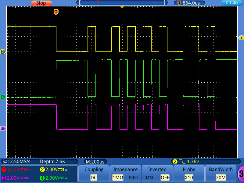
Transitions are much faster.
-
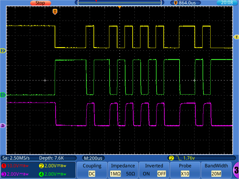
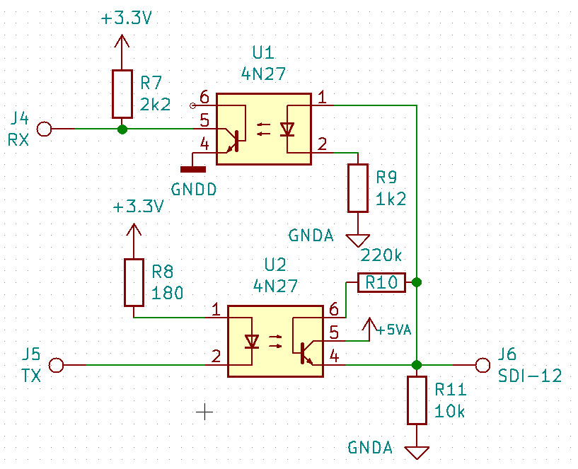
@robert-hh I made a breadboard set-up with the optocouplers according to the schematics below. Since I do not have a SDI-12 device, I can only rate it by the intrinsic loop-back (what is sent, will also be received). The picture below shows the timing: yellow is Tx, green is the SDI-12 bus line, pink is RX. The optocoupler used is a 4N27 device. The voltage at the SDI-12 line is 5V. But due to the isolation, that does not matter much. Only the resistor values may have to be adapted.
For that set-up, I changed the resistor values a little bit. The 4N27 has a relatively low current transfer ratio, which required a lower value of R8. A 4N25 might work better. The new schematics is below. R10 improves the switch off timing, R11 the off level.
-
@tttadam The Teros device only sends a UART message once after power on. Since according to the Teros data sheet the high level is 3.6V, you do not need the level shifter. In fact, the level shifter you use may make things worse.
After the first message, the Teros device changes the polarity. That will be seen by the UART as start bit, and so it will constantly try to receive bytes. WIth the given set-up, you only can receive one message after power up of the Teros devuice, and then you must discard every else until the next power cycle of the Teros device.
-
@robert-hh okay, I just hooked on an UART port with a level shifter.
This is what I got:
b'\x80\x00\x00\x80\x00\x00\x00\x00\x00\x00\x80\x00\x00\x00\x80\x00\x80\x00\x00\x00\x00\x00\x00\x00\x00\x80\x00\x00\x80\x00\x80\x80\x00\x00\x00\x00\x00\x80\x80\x00\x80\x00\x80\x80\x00\x00\x80\x80\x80\x00\x80\x80\x00\x00\x80\x00'But I am not sure, how does it make sense. Can you gave me some hint? :)
-
@tttadam I use two METER sensors with WiPy but I have them connected through a converter board. It communicates with the SDI-12 bus via the Pycom serial port.
http://www.inmojo.com/store/liudr-arduino-and-physics-gadgets/item/sdi-12-serial-logger-shield/
-
@tvetter1976 Thanks for the manual. That is interesting, especially in that the signal levels deviate from the SDI-12 spec. But that should work. Nevertheless, I will give the adapter with the optocouplers a try. Not that I need it, but since I suggested it, I would like to know if it works. It's just one € value of parts, even in a local store. I like the idea of isolation. With cable lengths of 5 to 75 m, noise and spikes can get an issue.
-
You can still to use the serial output from the sensor and directily read the measurement using the UART. You don't need sdi12 at all. The only thing you need to is to switch on/off the senor. Then the sensor will send its measurement. The logic is not invereted. Why is this not an option for you? Also the digital output voltage output from Terros 12 is only 3.6V and not 5V.
From the manual:
http://manuals.decagon.com/Integrator Guide/18224 TEROS 11-12 Integrator Guide.pdf
"DDI SERIAL INTRODUCTION
The DDI serial protocol is the method used by the METER data loggers for collecting data from the sensor. This protocol uses the data line configured to transmit data from the sensor to the receiver only (simplex). Typically, the receive side is a microprocessor UART or a general-purpose I/O pin using a bitbang method to receive data. Sensor measurements are triggered by applying power to the sensor"
-
@tttadam Another variant with two optocouplers, which has the advantage that is completely isolates the SDI-12 wire from the WiPy. Given that these wires can be long, that may be useful.
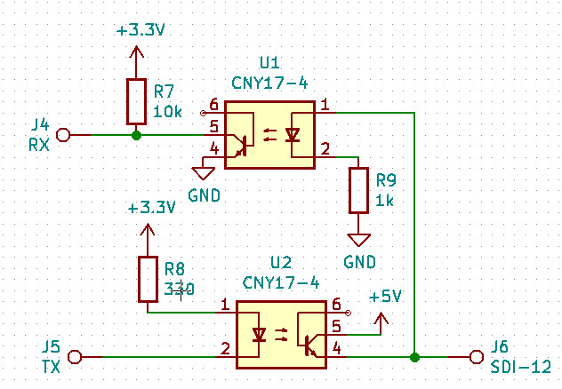
There are also devices with two couplers in one package, like the ILD74, but the CNY17 is more common. Since it is operated in a digital mode, the actual device is less critical.
-
@tttadam So, what you need is not only a level shifter. If you compare the interfaces you see quite a number of differences:
SDI-12:
a) Level 0 and 5 V
b) Halfduplex
c) Inverted
d) Load must be between 1 and 2 kOhmWiPy:
a) Level 0 and 3.3 V
b) Full Duplex
c) Straight
d) Load > 200 OhmFor a), a level shifter might work
for b) That has a hardware and software part. If you do the hardware right, if serves also for a) and c). The software part is easy. You just have to cope with the fact, that you will also receive what you have sent.
for c), you need to invert, unless you change the WiPy firmware
for d) minor problem.
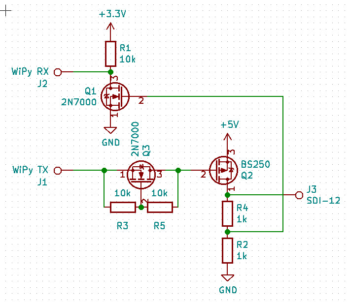
So, lets look for a solution to that. What comes into my mind is a circuit with two transistors and a few resistors.
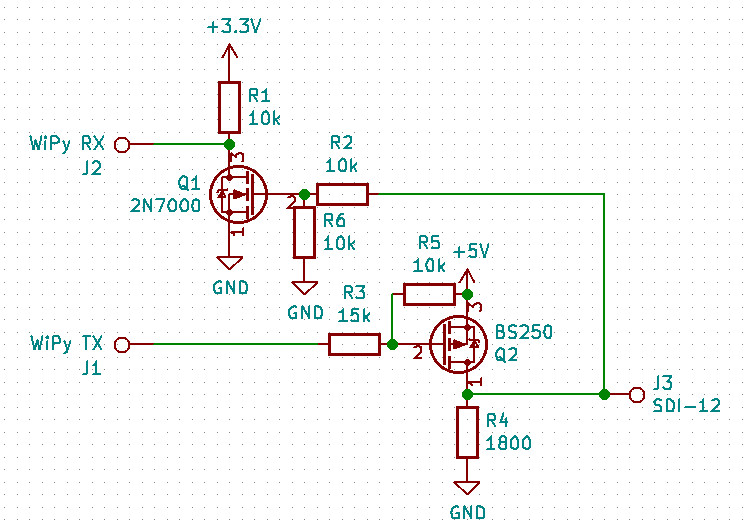
Instead of the 2n7000 you can also use a small signal npn transistor (e.g. 2N3904, BC547), instead of the BS250 a small signal pnp transistor (e.g.2N3906, BC557). That circuit should shift the levels, invert the signals and provide a proper impedance for SDI-12. The ration of R3 and R5 has to be chosen, such that the SDI line is low when the TX line is high.
-
@tttadam A diagram of the wiring with labels about what is what would be more helpful than a picture of a few wires.
-
Okay, so I facing with this topic again. (I put it into the drawer for some time, but it's on my desk now again)
So I am using a level shifter.
Also if I am right I need to use an external power source to power the teros 12, I use a 1.5A usb brick.
But the wiring is still not clear to me.
This is what I come up with. I don't want to fry it so first I would like to ask the community.
Thanks,
-
@Pesien I made a PR for inverted UART signals. It is here:
https://github.com/pycom/pycom-micropython-sigfox/pull/310
