SCT-013 current sensor
-
Hi guys,
Please, somebody has used a SCT-013 current sensor, were you able to get it to work?
Can you help me kindly share your code micropython?
I have problems reading the alternate voltage !
Thanks a lot
-
@Stefano-Floriani That's better. The capacitor worked here as a means to suppress noise. You can also increase the value of R7 to 27k. Then the value should be at about 150.
-
-
@Stefano-Floriani At the output of the 390k resistor (input of the Photocoupler) there should be the diodes voltage, which is about 1 Volt AC. Over the 390k resistor you should have 230V.
At the 10k resistor a good voltage is 2 V peak-peak or ~0.7 V AC.
-
Please, How many volts should there be at the output of the 390k resistor?
-
-
@Stefano-Floriani You could try to use other optocouplers, like 4N37, which has a higher current transfer ration (CTR). But again, this circuitry is using a chip designed for digital mode in an analog mode. That makes finding the right values difficult.
Edit: Other devices with higher CTR: CNY17-4
-
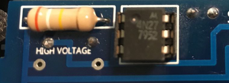
@Stefano-Floriani Looks like a Motorola device. Comparing the data sheets, they look similar. The device I used seems to have a higher CTR, but not by a factor of 40 different.
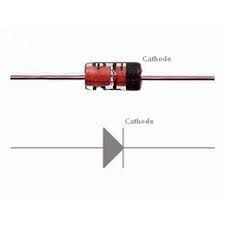
Ar you sure that you assembled the diode D1 in the right direction? If not, the LED current will be way lower.P.S.: The PCB design is dangerous! There is not a sufficient distance between the high voltage and low voltage side! Traces from the HV side MUST NOT lead to the LV side. And in a safe design there would also be a cut in the PCB below the chip between the HV and LV side.
-
-
@Stefano-Floriani Obviously you are running without load. Then the phase is not stable. But the value for voltage is still too low to be of use. What type of optocoupler are you using? I used a 4N27 type.
This kind of circuitry is hard to set up without any kind of measuring tool.
-
@robert-hh
this is the result running your script:
run()
(0.07947586, 5.907588, -0.961557) 0.5722438
(0.0303492, 5.957881, -1.419681) 0.1505412
(0.05318971, 5.931093, 0.2570791) 0.9671368
(0.08792933, 6.089819, -0.7879818) 0.7052775
(0.07133265, 5.925827, -0.5397768) 0.8578235
(0.1326455, 5.954846, -0.7830648) 0.7087548
(0.1046322, 5.97505, -0.6961006) 0.7673484
(0.09087696, 5.942791, -0.4167922) 0.9143923
(0.02481544, 5.990963, 2.182606) -0.57435
(0.08708447, 6.019161, 0.1956226) 0.9809269
average: 0.07623314 SDev: 0.03126099
I have used two resistor 390k ,10k at one watt .
-
@Stefano-Floriani I tested with the values in the schematics. But the optocouplers vary a lot between individual items and families. So the resistor values have to be determined for each and every item.
Thats one of the reasons I suggested using a small transformer. The variation in the transfer ratio of small transformers at their nominal load is way lower, only like 10%.
-
I'm so sorry, I thought you did the tests with the resistances, I don't have the equipment or material to try.
Thanks you
-
@Stefano-Floriani In that case the signal at P14 is way too small. For 230 V you should get a reading in the range of about 150 for a 9 bit ADC setting (see the chart and table in my previous post).
You can either reduce the value of the 390k resistor R6, or increase the value of the 10k resistor R7. You may also try to remove C4, because that one also reduces sensitivity. When the setting is right, you should measure with an multimeter an AC voltage of about 0.7 V~.
The transfer ratio of optocouplors vary a lot.
-
@robert-hh
Dear Robert,
The reading voltage with external voltmeter it's:
At 230 v and U from value[1] it's from 4
At 220 v and U from value[1] it's from 2How can I find the right formula?
Thanks a lot
-
@Stefano-Floriani The values returned by acq.reading are the two values from P13 and P14 and the phase difference phi between the signals at P13 and P14. So if P13 is connected to the SCT013 sensor, and P14 to the voltage sensor, you will get the current I from value[0], and the voltage U from value[1]. The number in value[2] can then be used to calculate the effective power consumed by the load, which is
Peff = U * I * cos(phi)
with I derived from value[0], U derived from value[1] and phi being value[2], which already has the proper scaling. The number cos(phi) is called the power factor. It is 1 for pure resistive loads, and 0 for pure capacitive or inductive loads. Values close to 1 are common, values close to 0 are rare.
-
@robert-hh
Hello,
I built my electronic circuit, now how should i use the result of the value [2] to get the correct voltage?value = acq.reading("P13", "P14", 500)
print(value[2])Thank a lot
-
Note. BE CAREFUL when testing to avoid an electric shock! I used an isolating variable output transformer for my tests to be safe.
Watts: the only part of interest is R6. So you have:
P = 230 * 230 / 390000 0.136 W
So that is negligible. The critical property of R6 is voltage capability. You have to get a 350V RMS type. That's typically better for higher power resistors. So get a 0.5W or 1W type.
The value of the resistor is to be determined. Since the transfer ratio of the optocoupler varies, you have to select a proper value such that at 230 V the output at R7 is about 2Vpp. You need an oscilloscope to tell. If you just have a Multimeter, use 0.7V AC. Below is a modified script capturing data from P13 and P14 (current and voltage). It returns the raw values and the phase difference between the two signals. That phase difference may have an offset, since the voltage signal is only half of the sine wave.
#
import gc
import math
import array
from utime import sleep_ms, sleep_us, ticks_us, ticks_diff
from machine import ADC, Timer, idle, enable_irq, disable_irq, Pin, SPI

#
# acquire ADC values. The paramters of the constructor are:
# 1. the mains frequency (number, typically 50 or 60)
# 2. the sampling period (ms). The default is 2 ms.
#
class Acquire:
    def __init__(self, freq=50, *, sample_period=2):
        self.sample_period = sample_period
        self.omega = 2.0 * math.pi * freq / (1000 / sample_period)
        self.coeff = 2.0 * math.cos(self.omega)
        self.freq = freq
        self.adc = ADC(bits=9)

    def start(self, pin1, pin2, time=200):
        gc.collect() # avoids automatic gc during sampling
        self.pin_adc1 = self.adc.channel(pin=pin1, attn=ADC.ATTN_11DB)
        self.pin_adc2 = self.adc.channel(pin=pin2, attn=ADC.ATTN_11DB)
        self.samples = time // self.sample_period

        # Test code for creating the artificial signal for phase noise
        # self.pi_f = (2 * math.pi * self.freq) / 1000000  # angle step per us
        # self.start_us = ticks_us()

        self.count = 0
        self.busy = True
        self.q1_1 = 0.0
        self.q2_1 = 0.0
        self.q1_2 = 0.0
        self.q2_2 = 0.0
        self.alarm = Timer.Alarm(self.read_adc, 0, us=(self.sample_period * 1000 - 3), periodic=True)

    def stop(self):
        self.alarm.cancel()

    def read_adc(self, alarm):
        state = disable_irq()
        v1 = self.pin_adc1()
        v2 = self.pin_adc2()
        # Test code using an artificial Signal
        # v1 = math.sin(ticks_diff(ticks_us(), self.start_us) * self.pi_f)
        # v2 = math.sin(ticks_diff(ticks_us(), self.start_us) * self.pi_f)
        enable_irq(state)

        self.q0_1 = v1 + self.coeff * self.q1_1 - self.q2_1
        self.q2_1 = self.q1_1
        self.q1_1 = self.q0_1

        self.q0_2 = v2 + self.coeff * self.q1_2 - self.q2_2
        self.q2_2 = self.q1_2
        self.q1_2 = self.q0_2

        self.count += 1
        if self.count >= self.samples:
            self.alarm.cancel()
            self.busy = False

    def result(self):
        while self.busy == True:
            sleep_ms(self.sample_period)

        real = self.q1_1 - self.q2_1 * math.cos(self.omega)
        imag = self.q2_1 * math.sin(self.omega)
        amplitude_1 = 2 * math.sqrt(real * real + imag * imag) / self.count
        phase_1 = math.atan2(real, imag)

        real = self.q1_2 - self.q2_2 * math.cos(self.omega)
        imag = self.q2_2 * math.sin(self.omega)
        amplitude_2 = 2 * math.sqrt(real * real + imag * imag) / self.count
        phase_2 = math.atan2(real, imag)
        #
        diff = 40e-6 * 2 * self.freq * math.pi # phase diff caused by 40µs sampling delay
        phase = phase_1 - phase_2 - diff #
        if phase > math.pi:
            phase -= 2 * math.pi
        elif phase < -math.pi:
            phase += 2 * math.pi
        return amplitude_1, amplitude_2, phase

    def reading(self, pin1, pin2, time):
        self.start(pin1, pin2, time)
        return self.result()
#

def run(period = 500, n=10):
    acq = Acquire(50.0, sample_period=1) # 50 Hz
    l=[]
    for _ in range(n):
        value = acq.reading("P13", "P14", period)
        l.append(value[0])
        print (value, math.cos(value[2]))
    avg = sum(l)/n
    sqsum  = 0
    for _ in l:
        sqsum += (_ - avg) * (_ - avg)
    print ("average: ", avg, "SDev:", math.sqrt(sqsum/n))
-
Hi Robert,
thanks for you support,I try this way , please, the componets how many watts and tolerances?
Thanks advance
-
@StefanoF So I made a few tests in the 230V range. Changed circuit with R=390k and a capacitor for less noise:
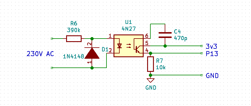
The transfer function is as below:
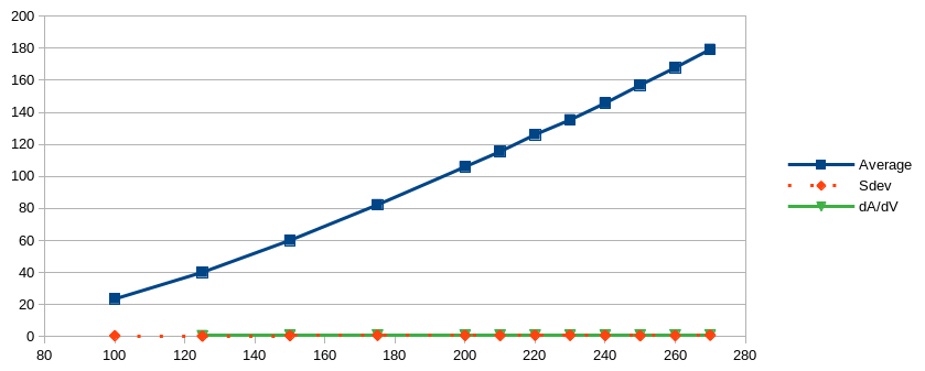
Not too bad, almost linear in the upper range. What stays is the huge temperature dependency.
Because the green and red line are almost identical, here the table:Volt Average Sdev dAvg/dVolt 100 23,56 0,55 125 40,18 0,33 0,6648 150 60,11 0,6 0,7972 175 82,32 0,83 0,8884 200 106 0,778 0,9472 210 115,5 0,68 0,95 220 126,1 0,832 1,06 230 135,3 0,88 0,92 240 145,73 0,73 1,043 250 157 0,549 1,127 260 167,88 0,638 1,088 270 179,28 0,883 1,14