Welcome to the Pycom forum Forum
    • \[\[global:header.categories\]\]
    • \[\[global:header.recent\]\]
    • \[\[global:header.tags\]\]
    • \[\[global:header.popular\]\]
    • Login

    Explore Pybytes | Official Documentation | Report a Firmware Bug/Issue | GitHub

    SCT-013 current sensor

    Scheduled Pinned Locked Moved LoPy
    37 Posts 3 Posters 162 Views 3 Watching
    Loading More Posts
    • Oldest to Newest
    • Newest to Oldest
    • Most Votes
    Reply
    • Reply as topic
    Log in to reply
    This topic has been deleted. Only users with topic management privileges can see it.
    • robert-hhR Offline
      robert-hh @Stefano Floriani
      last edited by

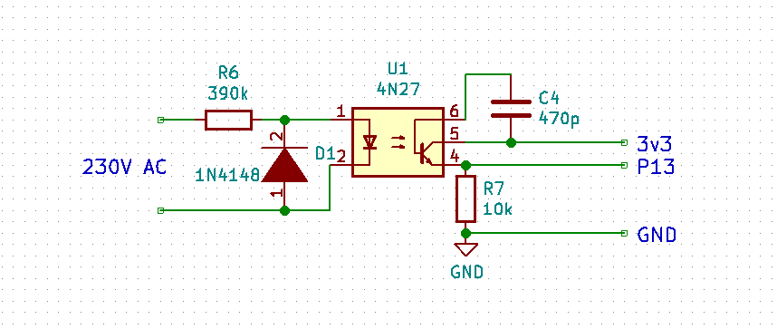
      @Stefano-Floriani I tested with the values in the schematics. But the optocouplers vary a lot between individual items and families. So the resistor values have to be determined for each and every item.
      Thats one of the reasons I suggested using a small transformer. The variation in the transfer ratio of small transformers at their nominal load is way lower, only like 10%.

      S 1 Reply Last reply Reply Quote 0
      • S Offline
        Stefano Floriani @robert-hh
        last edited by Stefano Floriani

        @robert-hh
        this is the result running your script:
        run()
        (0.07947586, 5.907588, -0.961557) 0.5722438
        (0.0303492, 5.957881, -1.419681) 0.1505412
        (0.05318971, 5.931093, 0.2570791) 0.9671368
        (0.08792933, 6.089819, -0.7879818) 0.7052775
        (0.07133265, 5.925827, -0.5397768) 0.8578235
        (0.1326455, 5.954846, -0.7830648) 0.7087548
        (0.1046322, 5.97505, -0.6961006) 0.7673484
        (0.09087696, 5.942791, -0.4167922) 0.9143923
        (0.02481544, 5.990963, 2.182606) -0.57435
        (0.08708447, 6.019161, 0.1956226) 0.9809269
        average: 0.07623314 SDev: 0.03126099
        I have used two resistor 390k ,10k at one watt .

        robert-hhR 1 Reply Last reply Reply Quote 0
        • robert-hhR Offline
          robert-hh @Stefano Floriani
          last edited by

          @Stefano-Floriani Obviously you are running without load. Then the phase is not stable. But the value for voltage is still too low to be of use. What type of optocoupler are you using? I used a 4N27 type.
          This kind of circuitry is hard to set up without any kind of measuring tool.

          S 1 Reply Last reply Reply Quote 0
          • S Offline
            Stefano Floriani @robert-hh
            last edited by

            @robert-hh test.jpg

            robert-hhR S 3 Replies Last reply Reply Quote 0
            • robert-hhR Offline
              robert-hh @Stefano Floriani
              last edited by

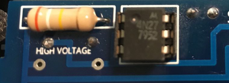
              @Stefano-Floriani Looks like a Motorola device. Comparing the data sheets, they look similar. The device I used seems to have a higher CTR, but not by a factor of 40 different.
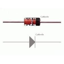
              Ar you sure that you assembled the diode D1 in the right direction? If not, the LED current will be way lower.

              P.S.: The PCB design is dangerous! There is not a sufficient distance between the high voltage and low voltage side! Traces from the HV side MUST NOT lead to the LV side. And in a safe design there would also be a cut in the PCB below the chip between the HV and LV side.

              S 1 Reply Last reply Reply Quote 0
              • robert-hhR Offline
                robert-hh @Stefano Floriani
                last edited by robert-hh

                @Stefano-Floriani You could try to use other optocouplers, like 4N37, which has a higher current transfer ration (CTR). But again, this circuitry is using a chip designed for digital mode in an analog mode. That makes finding the right values difficult.

                Edit: Other devices with higher CTR: CNY17-4

                1 Reply Last reply Reply Quote 0
                • S Offline
                  Stefano Floriani @Stefano Floriani
                  last edited by

                  @robert-hh
                  15c210fe-0905-488a-9091-0fa7aaf62fac-image.png

                  download.jpg

                  I have assembled the diode D1 the right directiont?

                  THanks a lot

                  1 Reply Last reply Reply Quote 0
                  • S Offline
                    Stefano Floriani @robert-hh
                    last edited by

                    @robert-hh

                    Please, How many volts should there be at the output of the 390k resistor?

                    robert-hhR 1 Reply Last reply Reply Quote 0
                    • robert-hhR Offline
                      robert-hh @Stefano Floriani
                      last edited by

                      @Stefano-Floriani At the output of the 390k resistor (input of the Photocoupler) there should be the diodes voltage, which is about 1 Volt AC. Over the 390k resistor you should have 230V.

                      At the 10k resistor a good voltage is 2 V peak-peak or ~0.7 V AC.

                      S 1 Reply Last reply Reply Quote 0
                      • S Offline
                        Stefano Floriani @robert-hh
                        last edited by

                        @robert-hh

                        I've remove C4 (470p) now is value[1] it's 50.99931,

                        Bye

                        robert-hhR 1 Reply Last reply Reply Quote 0
                        • robert-hhR Offline
                          robert-hh @Stefano Floriani
                          last edited by

                          @Stefano-Floriani That's better. The capacitor worked here as a means to suppress noise. You can also increase the value of R7 to 27k. Then the value should be at about 150.

                          1 Reply Last reply Reply Quote 0

                          Hello! It looks like you're interested in this conversation, but you don't have an account yet.

                          Getting fed up of having to scroll through the same posts each visit? When you register for an account, you'll always come back to exactly where you were before, and choose to be notified of new replies (either via email, or push notification). You'll also be able to save bookmarks and upvote posts to show your appreciation to other community members.

                          With your input, this post could be even better 💗

                          Register Login
                          • 1
                          • 2
                          • 2 / 2
                          • First post
                            Last post

                          Pycom on Twitter

                          Pycom