Power Consumption and Current Measurement
-
Hi Everyone
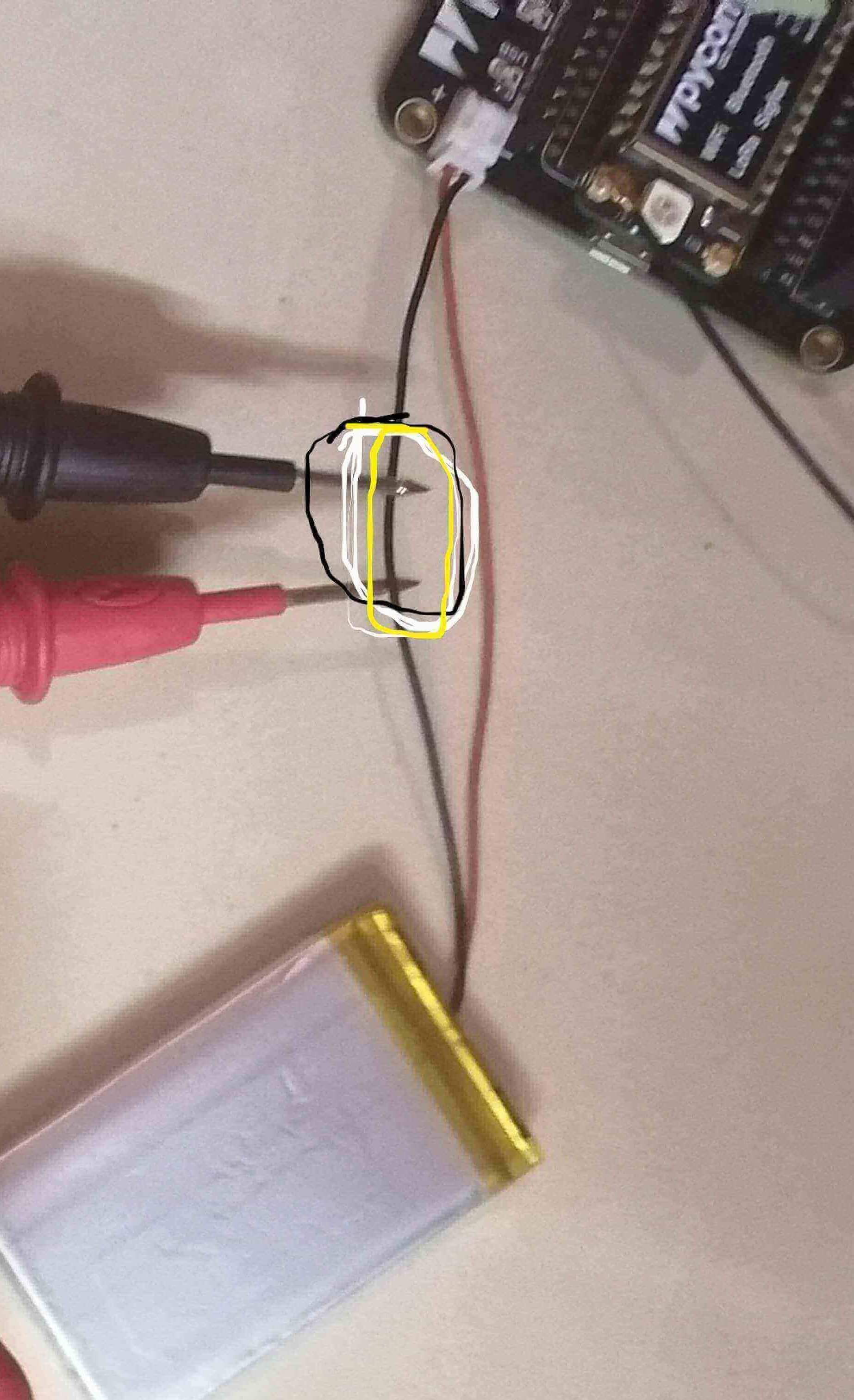
What could be the way of measuring power consumption on my lopy4 using the multimeter? Since Power = current x voltage, I know I have to measure the current and the voltage. To measure current, I noticed that I have to make the multimeter to be a part of the circuit (in series) so, I was thinking of breaking the circuit by cutting one of the battery wires then connect the multimeter probes to the cut wire. Can this be a correct way of measuring the current? I would also like to know other approaches of measuring current using a multimeter. Please see the picture below.
Thank You
Njabulo
-
Thank you so much @Gijs, I can now read the voltage successfully on my expansion board.
-
On the expansionboard 3.1, P16 is connected through to the battery, through a voltage divider (depending on the hardware revision, its either 1M, 1M or 115k & 56k). there's some discussion on the topic here: https://forum.pycom.io/topic/6943/measure-a-lipo-battery-voltage/
-
Thanks a lot @jcaron I was not aware of the ADC library, let me take advantage of it.
-
@mthethwansm For the you don't need to connect your probes anywhere, you just use the relevant library to get the voltage from the ADC.
If you want to use your meter to measure voltage, you need to have your probes on each of the two wires coming from the battery. Not sure there are any pins connected to VBAT+, though there may be a test point? Probably depends on the exact board and version you are using.
-
Thank you so much @jcaron. To measure the voltage for the board using the voltage measuring circuitry available on the board, what are pins should I connect with the probes.
-
@mthethwansm to measure current, you can either:
- have the multimeter set to measure amps and inserted in series between the battery and the board, i.e. you cut the wire, connect one end to one of the probes and the other end to the other probe. There should be no direct connection between the two ends of the wire other than through the multimeter.
+-----+ | BAT |--------+ +---- +-----+ | | +-MM-+- cut the wire, and insert a resistor between the two ends. Connect the multimeter probes at the two ends, and set it to measure voltage. You can then find current by dividing the voltage measured by the resistance. It’s easier if you pick a round value such as 1 ohm or 10 ohms.
    +-----+
    | BAT |--------+-R--+----
    +-----+        |    |
                   +-MM-+
The second option is more practical than the first one in several cases:
- If you need to move the multimeter (to measure other things, such as the voltage, for instance)
- If you can't keep your probes in place (if you only have the probes shown on your picture, for instance)
- If you need to change ranges on your multimeter: changing the range while in series will usually mean an interruption of the circuit, which would power down the board for a short amount of time
Pick a resistor as small as possible to avoid a large voltage drop, taking into account the range of the multimeter and the expected current range.
Note that in this case you are measuring voltage across the resistor, not for the board. To measure voltage for the board you need to connect the two probes to the + and - leads. But you could also use the voltage measuring circuitry already available on the board for that.