New expansion board how it should looks like
-
Hi all.
As there was multiple posts in the past about expansion board "nice to have on".
But all propositions was only as a list of wishes what should contain without proposition in design.I have created then my own expansion board ;-)
Please consider to improve current expansion board (i talk only about expansion board not Pytrack, Pysense ...)
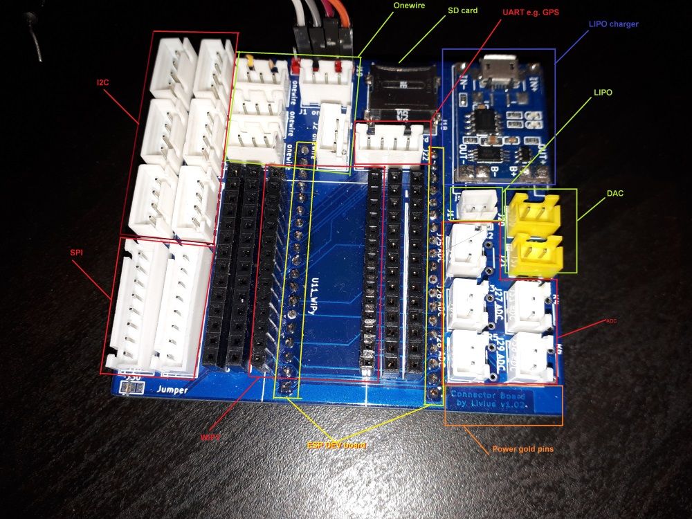
as current one is quite usless in term of speedup prototyping and testing sensors.This board speed up my all development. There are connectors for:
6xI2C
2xSPI
5xOneWire
5xADC
2xDAC
1xLIPO ph + charger
1xSD card
2xUART
1xWIPY connector
2xGold pin rows on both right and leftOf course above depend on what is set for pins in the code on e.g. Wipy,
and the purpose of the connectors can be changed. This is version 1.02 of the board.
And i have some improvement in design e.g. for 7x power goldpins 3V3 and GND in the place when on below images are now label with board name.
Its size is 78.7 x 69.8 mm and use JST XH it can be smaller with e.g. JST SH it can be 12mm smaller in both directions.This is how for me expansion board should looks like to speed up developemenet and testing sensors.
-
pcb
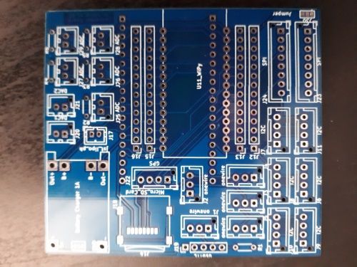
-
empty board with connectors mounted
-
board during testing
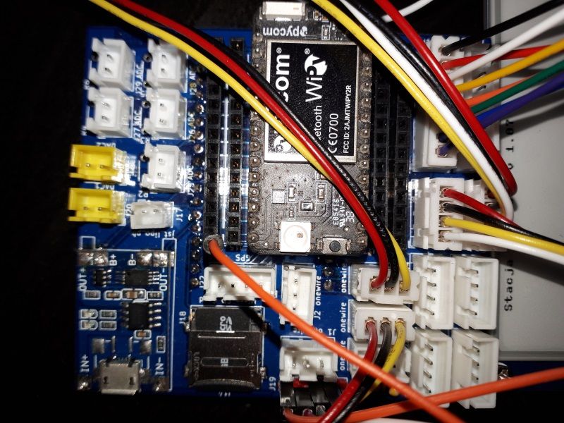
It contain also 1xESP32 Dev Kit C - on the bottom of the board.
PS. i am hobbyist not professional electronic ;-)
-
-
@jcaron
Yes. First battery connector is directly connected and then metter not work.
But if you plug battery to second connector then it have circuit throught this 2 gold pins.
Instead gold pins there can be something else soldered.I'd think ... on board edge
I have moved this gold pins by your advice to the edge of the board to have it better accessible.
-
@livius Great... I just don't figure where you connected the meter, to the two "header" pins between the two battery connectors? Not sure that would be the most practical, would it? I'd think pads on board edge you can use crocodile connectors on would be better? Though it probably depends what you want to connect, the header pins are probably better in some cases... Wonder what others think?
-
@jcaron said in New expansion board how it should looks like:
One thing missing on the expansion board is also a way to "insert" a meter between the battery and the rest of the board for current monitoring. Something with a jumper of some sort: jumper present, current goes directly, jumper off, you need to add your meter in between (with adapted connection ports, probably on board edge).
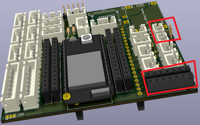
updated design - simple possibility to insert meter between battery.
I have thinked about jumper but realised more interesting (for me) solution.
There are 2 connectors for battery. One is direct, second is break by 2 goldpins where the meter go :)
And 2 header for power sources GND and 3V3.
Visualisation from Kicad as i have not updated version of real pcb yet as i have few old one.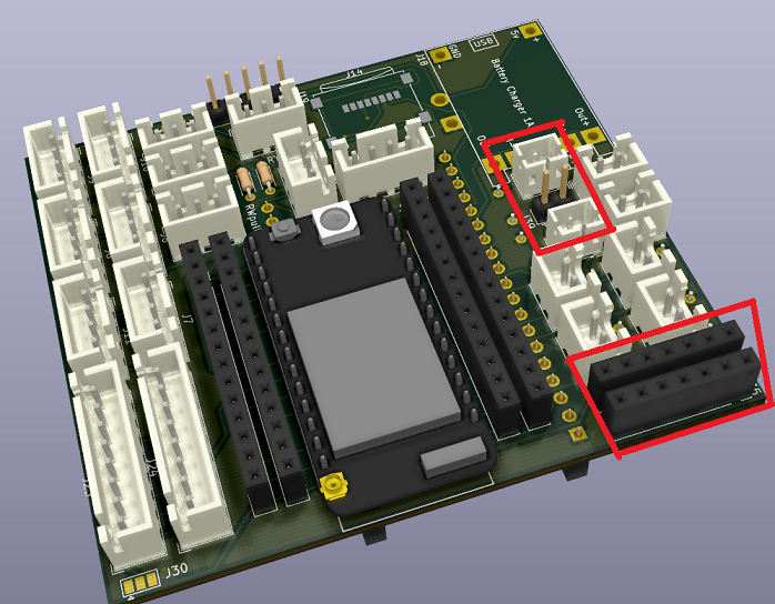
-
@jcaron said in New expansion board how it should looks like:
Grove and/or Qwiic/Stemma QT
I have thinked about Grove but i choose jst as i have many of them in the box ;-)
I simply prepare connection cables between multiple systems grove to jst, goldpin to jst ...
And now i am able to connect any sensor.I suppose many of your connectors are all connected together anyway? Having multiple connectors going to the same pins makes a bit too easy to connect multiple conflicting devices IMHO.
Yes, but "only" i2c have a problem here.
I have thinked about more i2c usage but i must resign from some other connector.
I did not want to add an expander.
I have thinked about removing 1 DAC or remove one SPI.
SPI + SD use most of the pins so there are only a few options :/One thing missing on the expansion board is also a way to "insert" a meter between the battery and the rest of the board for current monitoring.
I must add it to todo list, thx :)
-
@livius I like the presence of all those connectors, but I think I would have gone for Grove and/or Qwiic/Stemma QT connectors, so you can easily connect all the devices using those connectors that already exist out there.
I suppose many of your connectors are all connected together anyway? Having multiple connectors going to the same pins makes a bit too easy to connect multiple conflicting devices IMHO.
One thing missing on the expansion board is also a way to "insert" a meter between the battery and the rest of the board for current monitoring. Something with a jumper of some sort: jumper present, current goes directly, jumper off, you need to add your meter in between (with adapted connection ports, probably on board edge).
-
@Gijs said in New expansion board how it should looks like:
its the unlabeled 5 pin header next to the SD card reader
Yes, good catch, it is for programing
I'm not a big fan of the look and feel (sorry :) )
I am not proffesional electronic ;-) But it was designed to speed me up.
I design it in kicad.I can solder all sockets or only particular if not required in some project.
I can use it without modifications in weather station, controlling watering and tilting windows in a greenhouse or in a model of a car controlled with a cell phone.
I can fast play with new sensors connected securely as i really do not like universal pcb or breadboard ;-)
-
If there's more interest in (something like) this, let us know by leaving an upvote on the original post, or by adding your own suggestions of what you would like to be added below.
@livius Thanks for creating this interesting design. I'm not a big fan of the look and feel (sorry :) ), but I can imagine such a thing can be really useful in certain applications. A remaining question, I dont quite see how you can program the board? Im suspecting its the unlabeled 5 pin header next to the SD card reader, let me know!