Interfacing RS485 board to Wipy3.0 (with expansion board) fro Modbus implementation
-
Hello all,
I am wanting to use my Wipy as a modbus master to send and receive data to/from field devices. I plan on using a 3.3V SP485 breakout board (https://thepihut.com/products/rs485-board?variant=40242630721731)
I see there is a Pycom Modbus library, but theres limited & few complete forum discussions which conclude upon the success of this library. But im hopeful it will allow me to do what im wanting.
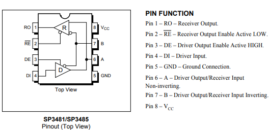
What im unsure of is how to interface with the board, specifically the pin labelled RSE (which I think is the RE & DE pin of the below RS3485 chip commoned together)
What function does this serve? Can I just tie them to a constant high or low source since my device will always be a master? Or does the Modbus library dynamically control the state of this pin (maybe this is the Ctrl pin in the following documentation: https://github.com/pycom/pycom-modbus/tree/master/uModbus)
Ideally I wouldnt want to loose an output pin, so if theres another way or board which would only require the Rx & Tx pins then please let me know.
Furthermore any RS485 examples would be much appreciated!
Thanks in advance!
-
Thanks for the info Elizar
So since as you say RS-485 physical protocol allows for multi-master networks, am I right in thinking the software protocol itself still only allows for a single master architecture?
I believe you are right when you say about requesting and listening (I think the master poll's a device's address to respond with the required data).I see the Modbus library also allows for TCP as opposed to 485. Can anyone suggest how I would physically connect the Wipy3.0 to a TCP network? This is something I pretty new to!
Thanks :)
-
RS-485 is meant to be a multi master bus. In contrast to an RS-232 there are no separate transmit (TxD) and receive (RxD) wires. Therefore there are enable signals for the sending and receiving buffers to avoid data collisions.
As one can see from the schematic symbol the control signals /RE and DE have different polarity (active low, active high) and may therefore be tied together. They may then be connected to a single cpu pin to switch the data direction (talk/listen). Your are right, this is probably the RSE signal.
Since the modbus protocol probably requires you to transfer datagrams in both directions (request something and listen for the answer) I would recommend to tie RSE to a digital I/O pin. So three pins are needed in total.
Besides the talk/listen switching RS-485 is much like a normal serial line.