Lopy and 5V relays
-
Hello,
Does anyone have the experience to use 5V relays like this using level converter like this.It is not always working. Sometimes the LED on relay in ON but I don't hear the "click" from the relay. I use a 5V , 2A usb transformer. The lopy and the relay are connected directly to the transformer. I checked the voltage on the relay: 4.90V, so it looks okay. Do you have any idea to fix my issue ? Thanks
-
@kots Even it that is true, it does not sound reasonable. G2 is used for the REPL communication. You might use another GPIO port for switching, but G2 seems to be an odd choice, as well as driving a step-up converter power input with a GPIO port, especially if a single transistor switch or digital gate is sufficient for the purpose.
-
@robert-hh thank you very much for your answer!
You are right about the G2 but i dont think it can cause an issue on lopy! I am only taking the 3.3V of that pin and step it up to 5V...
-
@kots Are you sure about G2, because that is the TX ouput of the UART0, and not meant to supply a buck converter.
About the solenoid: Since the relais is a simple switch, it does not power the solenoid. It can only switch the power to the solenoid on and off, but the appropriate power for the solenoid must be provided additionaly.
-
@robert-hh said in Lopy and 5V relays:
7cHC04
I made something different but i dont know if it really works. Let me share it with you. I use the type of relays that @alex89 mentioned, to drive a hunter solenoid.
I connect my lopy's G2 pin(expansion board) to this boost converter. Then i connect the output of my converter to the relay's shield Vin and Ground Pins. I power my relay through 5v pin of arduino Uno. And my relay works. I can hear it switching and the green led on the shield goes on and off as expected. What it doesnt work is the hunter solenoid. Any ideas?
-
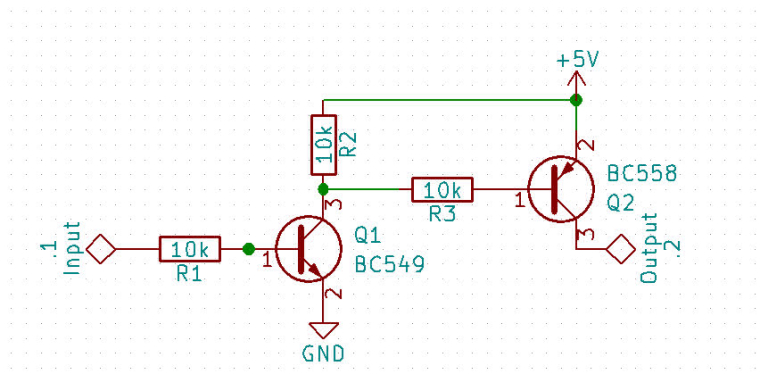
@alex89 That's correct. The transistor circuit replaces the level converter. And you need that 4 times.
You need both to supply sufficient current to the input w/o a high standby current.
You could use just one 2N3904, but then the resistor between Vcc and Collector would have to be much smaller, like 150..220 Ohm to get sufficient current into the input, and the logic level is inverted. So to switch the relay on, you'll need output a 0, and to switch it off, you'll need a 1. And the default state would be ON.
-
@robert-hh I have these: 2N3904/2N3906. So if I understood well, if I use these transistors, I don't need the logic level converter anymore ? Also, I will need 4 X 2N3904 and 4 X 2N3906 ; two transistors for each relay ?
Do you think it will work if I do this but using only one 2N3904 ? Why would I need the 2N3906 ?
-
@alex89 Equivalent parts for BC549/BC558 are:
2N2222/2N2907 or
2N3904/2N3906 or
.....
-
@alex89 The model of transistor is not very critical. You can use almost any npn and pnp small signal type. But as said, the 74hc04 is the more convenient choice.
The reason is, that the input of the relay board requires like 10 mA into GND to drive the LED in the Optocoupler on the board. Using the level converter, this current comes from the pull-up resistor in the converter, which is like 10k, resulting in am inrush current of about 20µA, which is too low to drive the optocoupler. The two diodes are connected in series, with a voltage of about 1.5 V each at 10mA, resultuing in a minium drivin voltage of 3.3 V
What you could try is to bridge the external LED and drive the input directly for the WiPy/LoPy. It can supply that current, and then the voltage required is within the output range of the unit.
-
@robert-hh I am doing this project in Ethiopia, I will never find this transistor here. What I don't understand is these kind of relays works well with raspberry pi which I think allows 15mA max. Also I don't understand why the driving current is too low as I connect directly the relay to my 5V power source. I am sorry to be a total noob in electronic...
-
@alex89 You would need a two transitor driver, like the half of an output bridge, e.g. like this picture. The transistors could be any small signal NPN/PNP type. But as said, you could also use a 7cHC04, which has 6 drivers in a single package, with no need to add any other analog components. Anf that chip is widely available. Almost any electronic stor should have it.
-
@robert-hh thank you for your answer. I can't understand all your explanations but I get your point. So something like this could work ?
I am also using one arduino sending sensor values to the lopy by UART, maybe it would be easier to connect the relay to the arduino. What do you think?
-
@alex89 It looks like the driving current is too low. Since there is no schematic, I have to look at the pictures to guess one. From the input side, you have to drive a two LES's in series, one on the board and one in the optocoupler, requiring a high level of about 4V and the driving current specified as 15..20 mA. Both the Lopy and the level converter cannot drive that. So you would need a strong driver like a simple two transistor ciruit (NPN + PNP or N-Channel + P-Channel Mosfet), which replaces the level converter. The N-type would do the level conversion, and the P-Type drives the current. Or simply a 74hc04 inverter/driver.
An (old) Arduino works, because it runs at 5V an can drive 40 mA.