LoPy + SP3485 + Modbus Lib Test. Register Read Error
-
Hi Everyone, I am testing the Modbus lib with a LoPy and a PowerMeter. I am using an SP3485 board as an interface between the LoPy and the Meter. For the code I use:
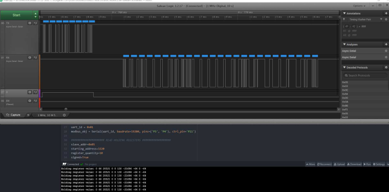
uart_id = 0x01
modbus_obj = Serial(uart_id, pins=('P3', 'P4'), ctrl_pin=('P11'))slave_addr=0x01
starting_address=0x50
register_quantity=1
signed=Trueregister_value = modbus_obj.read_holding_registers(slave_addr, starting_address, register_quantity, signed)
print('Holding register value: ' + ' '.join('{:d}'.format(x) for x in register_value))and the error that reports to me is:
File "main.py", line 71, in <module>
File "/flash/lib/uModBus/serial.py", line 125, in read_holding_registers
File "/flash/lib/uModBus/serial.py", line 84, in _send_receive
File "/flash/lib/uModBus/serial.py", line 60, in _uart_read
File "/flash/lib/uModBus/serial.py", line 41, in _exit_read
IndexError: bytearray index out of rangeCan someone help me or tell me if they came across this error?
Thanks.
-
@daniel Good afternoon, the modifications work perfect.
Best regards.
Mariano.
-
@daniel Tryed it today and it works without problems in my modules.
For some reason, the Sparkfun SP3485 fail safe feature don't appears to be working here. So i added pull up and down 1k resistors to RS485 line, as said in Analog Devices application note AN-960, and the module start to work correctly. So my problem is solved and your library works like a charm ;)
Best regards
Nelson Pinto
-
@daniel Tomorrow i'll try it again with Sparkfun module. I've been working with max485 module last days, done more them 50 thousand readings with only some random errors (less than 10).
Best regards
-
Hello,
After testing with several devices, we have seen that the best strategy for the control pin is the one in this commit: https://github.com/pycom/pycom-modbus/commit/6eb00535ef63fa1e4d38f16667779124f1d0a75f
Cheers,
Daniel
-
@neuromystix @daniel I think the best thing is to leave this parameter outside the lib so that you can modify them according to the RS485 converts. Modify the lib and I carry 1300 readings without problems.
Greetings.
-
@daniel I dont think it's necessary to adapt anything. Since only in Sparkfun module i need some adjustments. All the other modules worked fine, as yours. So leave the library as you published first, without any changes.
I tested baud rates 19200 and 38400, and everything worked fine with the original library.
With Sparkfun module ONLY, i changed _uart.wait_tx_done(2) to _uart.wait_tx_done(5) and added response = response[1:len(response)-1] inside _validate_resp_hdr, between raise OSError('no data received from slave') and resp_crc = response[-Const.CRC_LENGTH:]. Leaved it working for 2 hours, reading some registers each 5 seconds and dont get any error. So i think its something module related not about library ;)Best regards
Nelson Pinto
-
@Nelson thanks for testing all this. So, at the end, how does the timing for the control pin during transmit/receive should look like? Should we adapt the timing based on the baud rate (like 2ms fixed delay + the timing of 2 characters)?
Cheers,
Daniel
-
@daniel Hi.
Today i tested the three modules i have. Started with initial library without any changes. And using a Schneider IEM 3255 energy meter.
Module with auto flow control. Everything ok.
Chinese module with DE+RE enable pins. Also everything working, without any change in the original library.
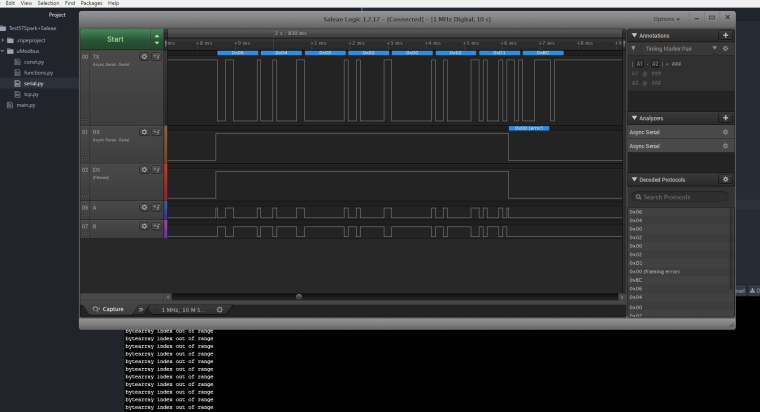
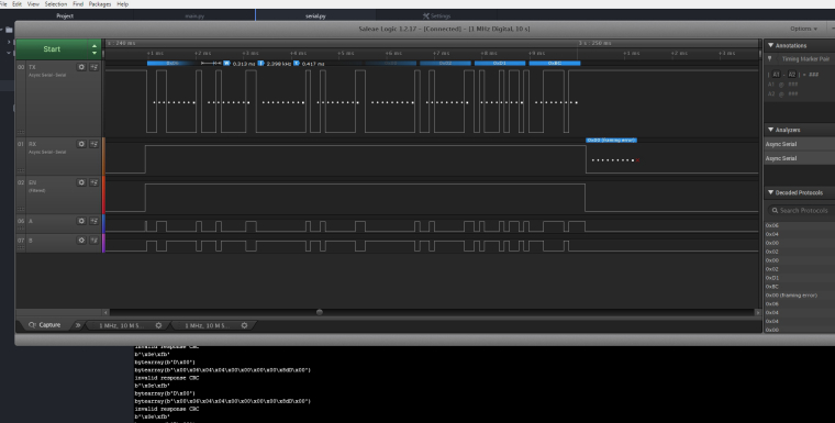
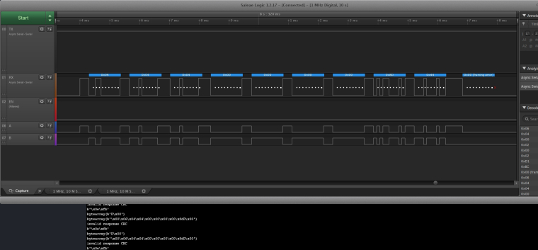
Then, the Sparkfun module. As always, getting CRC errors. When comparing the waveforms from this module with those from c25b, its easy to see from where the zeros come from. In the image the upper waveforms are from c25b and they are clean in both ends. Also, the TX pin stay HIGH when idle. In Sparkfun module TX pin is at LOW state when idle, so when UART is reading it always catch that zeros.
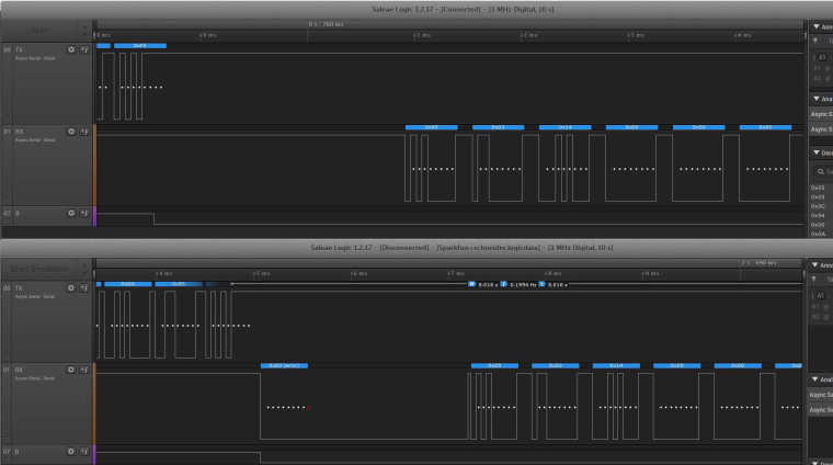
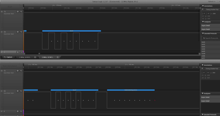
Sparkfun SP3485 datasheet says that when EN pin is LOW, if the difference between A-B modbus line is positive (A-B > 0.2 V), then TX output should be 1. When the difference is negative (A-B < 0.2 V), TX output should be 0. In case when nothing is connected in A-B, TX goes HIGH. Same behavior with MAX485 chip from c25b module.
If i left A-B floating in Sparkfun, nothing happens in TX which should go HIGH. In c25b its everytime HIGH, except when EN LOW and some data appears in A-B.So the problem was not in the library but in Sparkfun module behavior. Anyone who need to use one of those, have to delete that extra 0x00 bytes in the received data.
Best regards
Nelson Pinto
-
@daniel it always worked fine with a module that had auto flow control. But with this modules which have some sort of enable pins, there's always some troubles.
Anyway, the 0x00 problem is easy to solve, so if anyone else have the same thing just need to delete it.Tomorrow ill give some more feedback.
Best regards
Nelson Pinto
-
@Neuromystix thanks! We are tesing with some intersil devices and before and after that commit it always works. And we never get the extra zeroes before or after...
Please let me know the results of your next tests.
-
@daniel i checked your commit and the time.sleep_ms(5) should be outside the while not loop, or it wont work. And the machine.idle() stay there ;) (Just putting a image because Insert Code Block isnt working here)
Also, dont know if for any other baud rates that 5 ms will work. That's why ill try the Schneider module which have higher baud rates than this Eastron im using right now.
Best regards
Nelson Pinto
-
@Neuromystix great, thanks! Change made:
https://github.com/pycom/pycom-modbus/commit/72065c3da10ebdea9e78f83368353b633a36ed97
Cheers,
Daniel
-
@daniel Done
Chinese module, 240 readings without problem!
Sparkfun module, 280 readings (deleting 0x00 from the beginning and ending of the received data). No problems with it also.
Tomorrow ill try a different ModBus device (a Schneider energy meter) to check if everything works also.
The strange thing here is why the Sparkfun (sp3485 chip) add that two 0x00 bytes.Best regards
Nelson Pinto
-
@Neuromystix wow, thanks for the awesome feedback, well done with your tests!
We will modify the library to add the extra delay which in your tests seems to make it more robust. Can you try with timeout_chars=10 and see if it makes any improvement? Thanks again!
Cheers,
Daniel
-
Hello all,
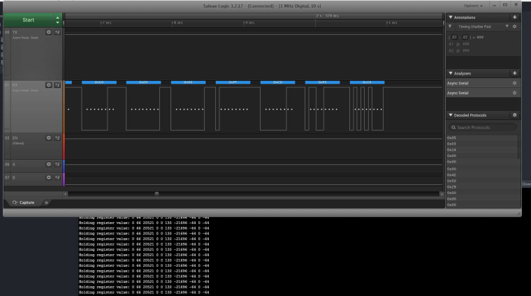
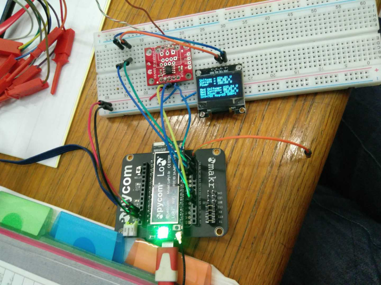
Today i started a different approach, using a logic analiser to check whats going on with the waveforms. My setup was a Sparkfun RS485 breakout board and a Eastron energy meter (baud=9600, parity even, 1 stop bit). Lopy was using pins P3 and P4 for UART and P11 for RTS. Using the new library, not changing anything i was always getting the "bytearray out of range" error. The waveforms showed me that the Modbus slave dont send any answer, because the RTS pin is lowered before the CRC part of the sending frame is finished.
I managed to overcome it changing the default _uart.wait_tx_done time from 2 to 5. 5 is the minimum that works here. I also tried to change the timeout_chars but dont get any result.
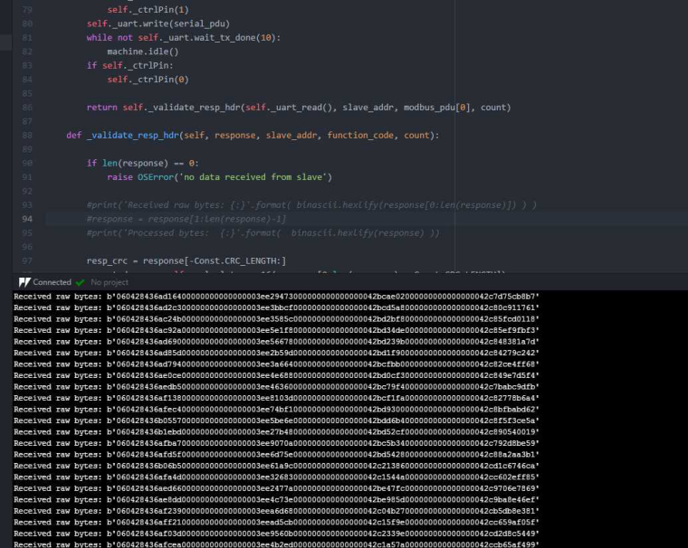
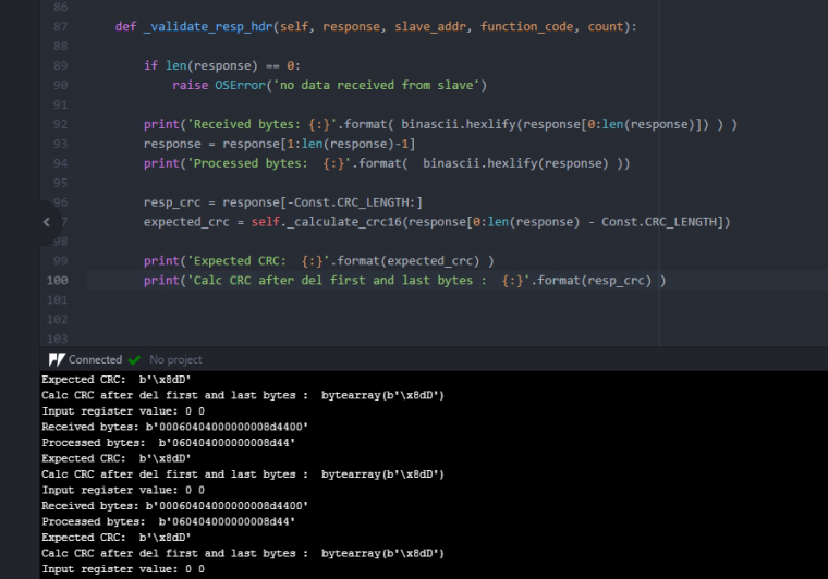
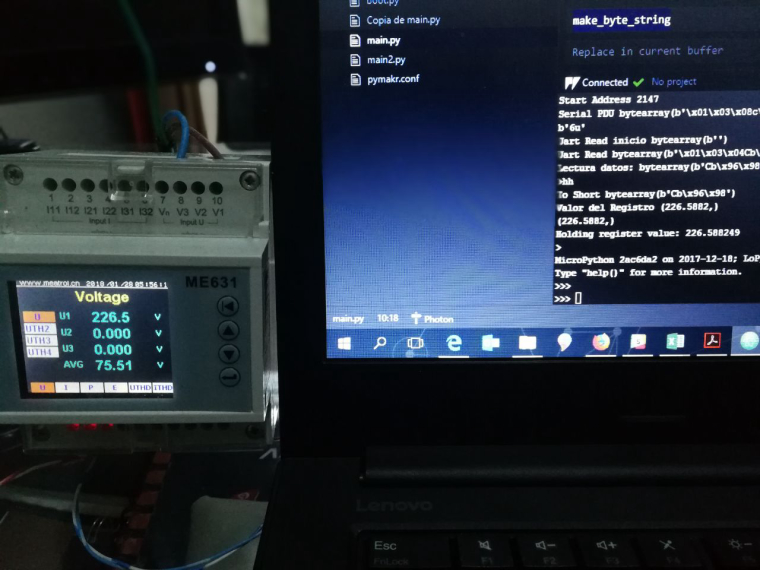
After that, im getting a answer from slave. Im reading 2 input registers (function code 0x04) which contain 0x0000, in address 0x04, slave id 0x06. The calculated CRC for that frame is 0x448D. Checking the received waveforms, its everything as expected.
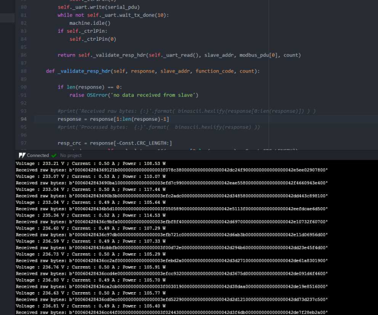
Putting a simple print inside _validate_resp_hdr, reveals that the content of the response last byte isnt 0x44, which is CRC high byte, so it will never validate the response. All the other fields are ok, except the first and last bytes which contain 0x00. So i removed this first and last bytes, and now it appears to be working fine.
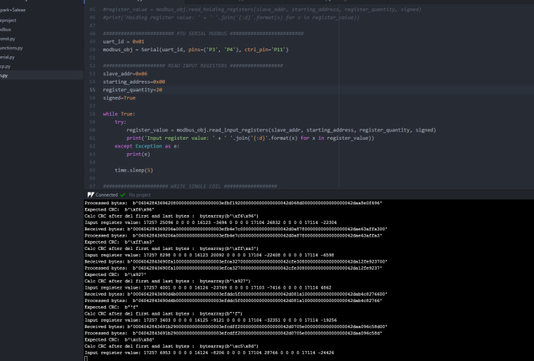
Here im continuously reading 20 registers without problems.
Hope it can help anyone. This shouldnt be the solution, however it worked for me ;)
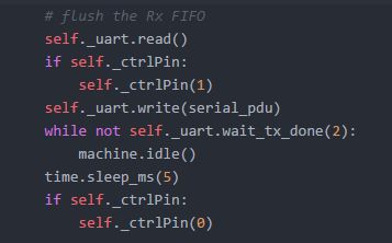
Update #1: Letting _uart.wait_tx_done(2) and adding a time.sleep_ms(2) before turn off the ctrl pin also worked here!
Update 2: Sometimes i get some CRC errors. For some reason uart_read dont catch all bytes.Forget it. I have changed timeout_chars to 2, to do some tests and i forget to put it back to 5! Since then its working fine again.
Update 3: I let it running for more than 700 modbus readings, using Sparkfun module and it worked fine, without any errors. I just get 1 error in the first reading, but ok with that.
Also tried a chinese cheap module (module name c25b with max485 chip) with enable pins. Strangely, with this, the readings dont get the first and last 0x00 bytes. So a changed my code for dont delete it, or i get the CRC error. Left the _uart.wait_tx_done(5), after trying to reduce it to 2 but getting some errors. It worked fine for more that 700 readings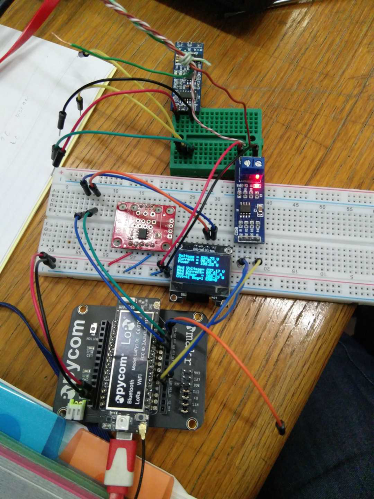
Best regards
Nelson Pinto
-
@daniel Hello everyone, I'm closer. Changing the speed to 38400, modifying the time_char parameter and the time delay, more than 50% of the reading attempts are correct. I update the LoPy to the new version and tomorrow I tell you.
-
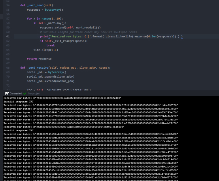
@daniel In a quick try with Sparkfun module still getting errors, but not always the same:
"bytearray index out of range
bytearray index out of range
bytearray index out of range
no data received from slave
invalid response CRC
bytearray index out of range
bytearray index out of range
bytearray index out of range
no data received from slave"Same code is working fine with the chinese module, just changing the ctrl_pin to "None". Tomorrow ill try it again.
Best regards
-
Hello,
Please use the latest firmware and the latest modbus library: https://forum.pycom.io/topic/2541/new-firmware-release-v1-15-0-b1
Cheers,
Daniel
-
@river I've been using one module with auto flow control and it works fine. Google "rs485 automatic flow control" or "xy-017 module" and you will see the module i've been using last week.