Correct formula for BATT monitoring on expansion board
-
Hi
What's the correct formula for Battery monitoring with a LoPy on the pycom expanysion board.
According to the datasheet it's a 1:2 voltage divider on the expansion board. And the ADC is 12bit (0-4095) and somewhere i was reading the the reference voltage is 1.4 voltso the formula i came up is:
adcVoltage = adcReading * referenceVoltage / adcResolution
battVoltage = adcVoltage * voltageDividerFactormy code is:
from machine import ADC

class LoPy(object):
    def __init__(self):
        self.adc = ADC()
        self.batt = self.adc.channel(attn=1, pin='P16')

    def get_batt(self):
        adcVoltage = self.batt.value()
        voltage = adcVoltage*3*1400/4095/1000
        # print("Battery V = %.3f" % voltage )
        return voltage
but the result is too high, while i measure 3.31 Volt with a fluke, the reading is 3.91 from the formula above
what could be wrong, my formula, the adc settings?
-
@robert-hh, the method function very well, thank you
-
@jclo13 The method channel.voltage() compensates for the attenuation. I just made a test, using the DAC output as input. Reading the 1.606V gave a result of ~1613 mV, so it's quite OK. Setting the DAC to 0 (=80mV) resulted in a reading of ~90 mV. The corresponding raw values were ~1890 and ~0.
-
@robert-hh yes, I did it, my question is basically if do I have to add the attn (11db=3.548V) to ADC value ?, because in the example of @roadfox, He multiplies by 1.334, that is the attn of 2.5 db.
-
@jclo13 Seems I was answering the wrong question.
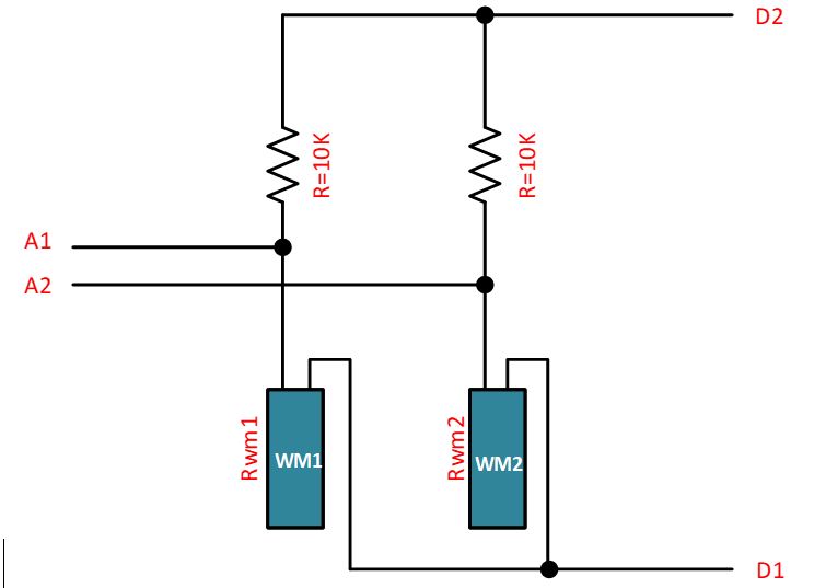
So the ratio is (R1 = 10k):
Vout/3.3V = Rwm1/(Rwm1 + R1)
after some transformation you get:
Rwm1 = R1 * (Vout /(3.3 - Vout))
-
@robert-hh thank you for answer so quickly, I am using an external voltage divider to obtain the value of the sensor, the sensor is part of the voltage divider, like the following figure, I use the 3v3 pin of the expansion board 2.0 to feed the circuit and I use an ADC pin to obtain the Vout, considering that the sensor varies I can´t get a fixed factor of the circuit, the objective is measured the resistance of the sensor using the Vout obtained by the ADC pin. How can I use a scaling factor? or what can I do, because I am using the direct value obtained by the ADC pin without considering the attn (11DB); I am a little confuse, do I need to add the attn value (11dB= 3.548V) to the ADC value?
Thank you
Jose
-
@jclo13 Vout of the ADC should be the voltage at the divider. But since you have to use a scaling factor anyhow, measure the voltage at the battery, take the result from the ADC and determine the scaling factor that. The ADC is pretty noisy, to better use an average value.
For expansion board 2 the divider is 115k/56k or 0.3275, giving 1.375V at 4.2V input, for expansion board 3 the divider is ~1M/1M, or 0.5, giving 2.1V at 4.2V input, so 11dB is the best choice.
-
hello @robert-hh,
is it necessary to compensate according to the attn the value obtained for the ADC? I am using a voltage divider to find the value of a sensor ( electrical resistance) and I am measuring whit a ADC pin the Vout of the Voltage divider, I am using an attn of 11 dB, do I have to compensate it? or did the Vout measured by the ADC pin is the real Vout of the voltage divider?, the Vin is 3.3v, what do you think could be the best att in the ADC pin?
thank you very much
Jose
-
-
Ho do i calculate the range from dB attenuation?
So far i have the following Table:
attn = 0 = ADC.ATTN_0DB = 0 db gain = range 0-1V
attn = 1 = ADC.ATTN_2_5DB = 2.5 dB = range 0-1.334V
attn = 2 = ADC.ATTN_6DB = 6 dB = range 0-1.995V
attn = 3 = ADC.ATTN_11DB = 11 dB = range 0 - 3.548VThe Voltage divider consist of a 56k and 116k resistor witch gives a factor very close to 3
so i changed my formula to: voltage = adcValue * 3 * 1.334 / 4095
and it's pretty accurate nowmany thanks
-
@roadfox The basic ADC range is 1V. You can set an attenuation factor of 2.5 dB, 6 dB or 11 dB (https://docs.pycom.io/chapter/firmwareapi/pycom/machine/ADC.html). 11 dB results in a 3.548V range. The voltage divider on the expansion board consist of a 56k/100k resistor pair, resulting in an attenuation factor of the resistors of 2.79, resulting in a range of 0..2.79V. So you have to use an attenuation factor of the ADC.
Update: I see that you use ATTN=1, which is 2.5 dB, resulting in a ADC range of 0..1.334 V. But the ADC on ESP32 is anyhow not very precise, and the impedances are not known. So you have to determine your own calibration factor.
Update 2: Some discussion about that is here:https://www.esp32.com/viewtopic.php?t=1045
A while ago I made similar measurements with a Lopy. The table below shows results for the 1 V range (attn=0).Input ADC 70 0 100 127 200 550 300 974 500 1820 700 2650 900 3510 1000 3933 1044 4095You see that it does not match the 0-1 rails. The same for attn=1. For attn=3 it is also non-linear above ADC readings of about 2500.