Speeding up HX711 Library
-
@robert-hh Wow many thanks for thinking along with me and spoonfeeding me the piece of code. I'm really grateful.
I've tried running your version of the driver/library and it runs in about 11 - 12 ms. That's indeed an improvement. Thanks for that. The actual values I still have to calibrate/compare to see if they make sense.
I think you are right about the HX711 board. Max. speed would be 80 Hz (If you cut the pcb line to enable that speed). So that would be the bottleneck in general then.
I hope you need the HX711 board for some project of your own or else i feel guilty that you ordered one...
Again muchos kudos for the effort.
-
@epstein actually the method read() takes less than 1 ms now, compared to 18ms before, so it is 20 times faster now. So if you see 11-12 ms, then you are timing something else too. Which method are you using for reading the value?
And no, don't worry about the HX711. It is just a few Euro. And I want to know, if my SPI idea works (50 times faster).
Edit: If you do not set the HX711 to high speed, it will provide values at 10Hz or every 100 ms. So how do you time the speed of reading a value? -
Hi Robert,
I used this:
while program == 1:
    pycom.rgbled(0x0000ff)
    p.append(hx.get_units(1))
    t.append(utime.ticks_ms())
    steps += 1
    if steps == 10:
        x1 = p[-3] - p[-2]
        x2 = p[-1] - p[-0]
        if x1 - x2 < 0 or test == True:
            program = 0
            dac.write(0)
            pycom.rgbled(0xFF0000)
            print('PROGRAM ENDED')
            print(t[2]-t[1])
            for T,P in zip(t,p):
                print('{},{}\n'.format(T-t[0],P))
I used utime.tick_ms for timing.
I see i used a different method to get the value.
Need to check my results with just read..Thanks!
-
@epstein I used this simple script for telling the speed:
from hx711 import * from utime import ticks_ms, ticks_diff # adapt the Pin names as required hx = HX711( "P10", "P11") def run(loops = 100): start = ticks_ms() for _ in range(loops): hx.read() print("Time per read:", ticks_diff(start, ticks_ms())/loops) run() -
@epstein I got my HX711 today and verified the code. The optimized variant is in a simple loop effectively not faster than the slow one, since the slow part of the code happens in the time frame, when the HX711 is anyhow not ready for a new reading.
But I could verify, that the reason for a major slow-down was the coding of the read method, in that during the high cycle of the HX711 clock IRQ is not disabled. In that case, it may happen that the high cycle of the clock is longer than 60 µs, and then the HX711 powers down, and needs400ms to get back to life. Even worse, this power cycle deletes the setting for gain and channel. The optimized code does not have this bug, and could also be simplified. Here is the code:from machine import Pin, enable_irq, disable_irq class HX711: def __init__(self, dout, pd_sck, gain=128): self.pSCK = Pin(pd_sck , mode=Pin.OUT) self.pOUT = Pin(dout, mode=Pin.IN, pull=Pin.PULL_DOWN) self.GAIN = 0 self.OFFSET = 1 self.SCALE = 1 self.set_gain(gain); def set_gain(self, gain): if gain is 128: self.GAIN = 1 elif gain is 64: self.GAIN = 3 elif gain is 32: self.GAIN = 2 self.pSCK.value(False) self.read() print('Gain set') def read(self): # wait for the device being ready while self.pOUT() == 1: pass # shift in data, and gain & channel info result = 0 for j in range(24 + self.GAIN): state = disable_irq() self.pSCK(True) self.pSCK(False) enable_irq(state) result = (result << 1) | self.pOUT() # shift back the extra bits result >>= self.GAIN # check sign if result > 0x7fffff: result -= 0x1000000 return result def read_average(self, times=3): sum = 0 for i in range(times): sum += self.read() return sum / times def get_value(self, times=3): return self.read_average(times) - self.OFFSET def get_units(self, times=3): return self.get_value(times) / self.SCALE def tare(self, times=15): sum = self.read_average(times) self.set_offset(sum) def set_scale(self, scale): self.SCALE = scale def set_offset(self, offset): self.OFFSET = offset def power_down(self): self.pSCK.value(False) self.pSCK.value(True) def power_up(self): self.pSCK.value(False)The variant using SPI is working too. It uses MOSI for the HX711 clock and MISO for the HX711 data. The SPI clock signal is not connected. Here is the copy
from machine import Pin, SPI class HX711: def __init__(self, dout, pd_sck, spi_clk, gain=128): self.pSCK = Pin(pd_sck , mode=Pin.OUT) self.pOUT = Pin(dout, mode=Pin.IN, pull=Pin.PULL_DOWN) self.spi = SPI(0, mode=SPI.MASTER, baudrate=1000000, polarity=0, phase=0, pins=(spi_clk, pd_sck, dout)) self.pSCK(0) self.GAIN = 0 self.OFFSET = 0 self.SCALE = 1 self.clock_25 = b'\xaa\xaa\xaa\xaa\xaa\xaa\x80' self.clock_26 = b'\xaa\xaa\xaa\xaa\xaa\xaa\xa0' self.clock_27 = b'\xaa\xaa\xaa\xaa\xaa\xaa\xa8' self.clock = self.clock_25 self.lookup = (b'\x00\x01\x00\x00\x02\x03\x00\x00\x00\x00\x00\x00\x00\x00\x00\x00' b'\x04\x05\x00\x00\x06\x07\x00\x00\x00\x00\x00\x00\x00\x00\x00\x00' b'\x00\x00\x00\x00\x00\x00\x00\x00\x00\x00\x00\x00\x00\x00\x00\x00' b'\x00\x00\x00\x00\x00\x00\x00\x00\x00\x00\x00\x00\x00\x00\x00\x00' b'\x08\x09\x00\x00\x0a\x0b\x00\x00\x00\x00\x00\x00\x00\x00\x00\x00' b'\x0c\x0d\x00\x00\x0e\x0f') self.in_data = bytearray(7) self.set_gain(gain); def set_gain(self, gain): if gain is 128: self.clock = self.clock_25 elif gain is 64: self.clock = self.clock_27 elif gain is 32: self.clock = self.clock_26 self.read() print('Gain set') def read(self): # wait for the device to get ready while self.pOUT() != 0: pass # get the data and set channel and gain self.spi.write_readinto(self.clock, self.in_data) # pack the data into a single value result = 0 for _ in range (6): result = (result << 4) + self.lookup[self.in_data[_] & 0x55] # check sign if result > 0x7fffff: result -= 0x1000000 return result def read_average(self, times=3): sum = 0 for i in range(times): sum += self.read() return sum / times def get_value(self, times=3): return self.read_average(times) - self.OFFSET def get_units(self, times=3): return self.get_value(times) / self.SCALE def tare(self, times=15): sum = self.read_average(times) self.set_offset(sum) def set_scale(self, scale): self.SCALE = scale def set_offset(self, offset): self.OFFSET = offset def power_down(self): self.pSCK.value(False) self.pSCK.value(True) def power_up(self): self.pSCK.value(False) -
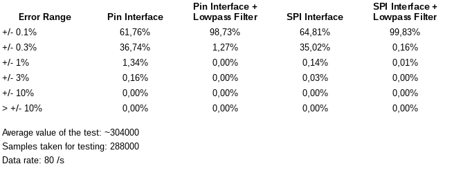
@epstein I made a few longer term measurement with the HX711 and a load cell. That one has a pretty low output voltage, so the output value was just at about 4% of the HX711 range. The results are in the table below. During that test over a set of about 5 million samples taken, not value was seen which was completely out of range. So the error state, which the geda implementation tries to avoid, was most likely caused by power down events. The lowpass filter is a simple 1 level filter of the kind:
value_out = tau * new_value + (1.0 - tau)*value_out
where the start value of value_out is either or some other reasonable value, and tau is the time constant in the range 0-1.0.
-
@robert-hh could it be possible to connect 4 load cells up with this library?
-
@jimpower Yes and no. Easy, if you spend 2 IO ports for each load cell. Data is input only, so you can use the analog input only for that. Then you can run all load cells in any mode.
Without changing the code, and if you run all devices in the same mode and have no speed demands, you can also share the clock gate with all devices, and read them one after the other.
By changing the bit bang code, you could read all 4 cells in one cycle within the read() method, by sharing the clock signal and just splitting up the data lines to four GPIO ports. After the pulse up/down cycle the code has plenty of time to read the state of all four load cells. The total time for reading would not be increased a lot. -
@robert-hh would it be better to use something like this Load Sensor Combinator with the expansion board would I still require the Load Cell Amplifier
-
@jimpower The load sensor combinator shown combines four half bridge load cells in a way, that it looks like one full bridge load cell. It is a pure passive board simplifying the wiring. The output has to be fed into a load cell amplifier and digitizer.

Hello! It looks like you're interested in this conversation, but you don't have an account yet.
Getting fed up of having to scroll through the same posts each visit? When you register for an account, you'll always come back to exactly where you were before, and choose to be notified of new replies (either via email, or push notification). You'll also be able to save bookmarks and upvote posts to show your appreciation to other community members.
With your input, this post could be even better 💗
Register Login