Editing an ultrasonic sensor library
-
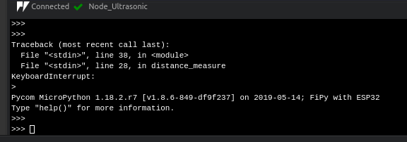
Hello guys, I'm having a problem implementing a code for my HC-SR04 ultrasonic sensor. I am using the Atom compiler and a Fipy.
import utime
import pycom
from machine import Pin, idle
# initialise Ultrasonic Sensor pins

echo = Pin('P19', mode=Pin.IN)
trigger = Pin('P20', mode=Pin.OUT)
trigger.value(0)

# Ultrasonic distance measurment
def distance_measure():
    # trigger pulse LOW for 2us (just in case)
    trigger.value(0)
    utime.sleep_us(2)
    # trigger HIGH for a 10us pulse
    trigger.value(1)
    utime.sleep_us(10)
    trigger.value(0)

    while echo.value() == 0:
        pass

    start = utime.ticks_us()

    while echo.value() == 1:
        pass

    finish = utime.ticks_us()

    distance = ((utime.ticks_diff(start, finish) * .034)/2)
    utime.sleep_ms(20)

    return distance

while True:
    distance = distance_measure()
    print(distance)
    time.sleep(1)
I'm using Core Electronics's code base: https://core-electronics.com.au/tutorials/the-things-network-ttn/hc-sr04-ultrasonic-sensor-with-pycom-tutorial.html
I haven't implemented the median distance function yet because I couldn't even calculate the instantaneous distance :(
I think the problem is in WHILE:
 while echo.value () == 0:
     pass
 start = utime.sticks_us()
 while echo.value () == 1
    pass
 finish = utime.sticks_us()
Because I changed the WHILE functions to IF and I was able to print some distances even if it's wrong.

If anyone can help me solve this problem, I will be very grateful!
-
This post is deleted!
-
@Lucas_Vieira Can you look at the signals, e.g. with a logic analyzer? You can get for about 10$, and the software from saleae.
Like this one: https://www.amazon.com/HiLetgo-Analyzer-Ferrite-Channel-Arduino/dp/B077LSG5P2/ref=sr_1_3?__mk_de_DE=ÅMÅŽÕÑ&crid=2I7VYOS7YP7KU&keywords=logic+analyzer&qid=1565038216&s=gateway&sprefix=logic+analy%2Caps%2C228&sr=8-3
-
@robert-hh
Thank you. I changed the pinout, but nothing happened.
-
@Lucas_Vieira FiPy uses P19 and P20 for the LTE modem. That will block the signals. Please use other pins, like P21 and P22.
-
@jcaron
I used a voltage divider at the ECHO pin input to get the 3.3V signal.
Pinout:
Vcc H04C-SR -> Fipy's Vin (5Vcc);
Gnd HC-SR04 -> Gnd Fipy;
Trigger -> P20 Fipy;
Eco -> P19 Fipy.
-
@Lucas_Vieira did you correctly take into account the fact that the FiPy runs at 3.3V while the sensor runs at 5V, as detailed in the tutorial?
Can you clarify how your power the FiPy and/or sensor and how you connected them together?