DIY a Compact RC Switch
-
Good day~all,
I have made a compact RC switch circuit,which built around the LM358 comparator reacts to a 50Hz PWM signal with a pulse width of around 1-2ms. If the reference voltage ( at pin2 of LM358 ) fixed by the 10K oitebtuineter is lower than the filtered signal voltage (at pin 3 of IC1), the comparator output goes high, relay driver BC547 (T1) is switched on and the 5V relay (RL1) works. The 100K reistor ( R5) provides small hysteresis to prevent the comparator from responding to every minor wavering in the voltage on the non-inverting input (pin 2) of the comparator. The aim I bluit this circuit is to control the on/off of lighting on radio control projects.
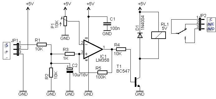
Well,Comparing with the above circuit,the only differences are that1).The relay driver(T1) I used is BC547A instead of BC547. This is the BC547A PDF.
2).My circuit has a 20K pot and it will not work,I am having a hard time figuring out the pin 2 input,giving a negative voltage.
Can anyone here help me?
Best regards~
-
@Len-Wang Since there is no negative supply, the voltage at pin 2 should always be positive. The difference between 10k and 20k for the pot is negligible. I would make R4 smaller, like 1 k. I do not know how much current the relay needs, but that should match the current gain of the BC547A (110-220) and R4.
What is the voltage at Pin 1, the op-amp output. Does it ever change?

Hello! It looks like you're interested in this conversation, but you don't have an account yet.
Getting fed up of having to scroll through the same posts each visit? When you register for an account, you'll always come back to exactly where you were before, and choose to be notified of new replies (either via email, or push notification). You'll also be able to save bookmarks and upvote posts to show your appreciation to other community members.
With your input, this post could be even better 💗
Register Login