SDI-12 Soil Moisture Probe Help
-
@jimpower I know this is an old thread but where are you getting the 1.8V ref from?
-
@robert-hh I'm not sure what happened but I changed my code back to the way it was before playing around with break times, uart timeout etc and it works.
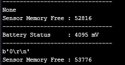
A note for anyone wanting to interface with SDI-12 with a LoPy you need to perform a gc.collect() after every read and then wait for 30secs before you can read from any other sensors.
@robert-hh thanks for your help with this it was pivotal to getting a working SDI-12 interface.
@AntonioValente thanks for your initial concept which lead to this solution.
-
@jimpower SInce the length of the response is not known, you need astrategy to tell when the respons eis complete:
- either the response has a known terminal symbol, like ! in the command, or \r\n, then you can read until you see that symbol, and wait as second condition for a long timeout. Waitung for \r\n is done by uart.readline().
- or you have to wait for a timeout.
The 75 char timeout seems reasonable, but to sort out implementation errors in Micropython, you could increase that for testing and see, if you receive a longer message. Thre reason I ask is, taht I faintly remember some discussion around the rx timeout of uart.read.
-
yes it says technical document "coming soon"
here is a snippet of my uart.readline()
Do you think this timeout_chars is correct? I wasn't sure what to put in here.
uart.init(1200, bits=7, parity=UART.EVEN, stop=1, timeout_chars=75)```
-
@jimpower Thanks. The code looks principly OK. What happens if you increase the receive timeout?
The documentation of the product is weird. Why cannot they include a proper protocol definition? Did you see b.t.w. CR/LF transmitted at the end of response messages?
-
I'm using an Enviropro EP100G-12 which has 12 rows of sensors at 10cm intervals, each row contains a temp, moisture and ec sensor.
http://enviroprosoilprobes.com/Files/EnviroPro_SDI-12_CommandsV2.pdf
http://enviroprosoilprobes.com/Files/EnviroPro_EPCU_User_ManualV3.pdf
import network
import time
import pycom
import machine
import gc
import socket
import utime
from machine import RTC
from machine import ADC
from machine import Pin
from machine import UART
from network import LoRa

execfile('/flash/Network/LoRa.py')

f_device = open('/flash/Config/Device_Details.txt', 'r')

device_setting = f_device.readline()
device_strings = [i.strip() for i in device_setting.split(',')]
f_device.close()

pycom.heartbeat(False)
rtc = RTC()
adc = ADC()
lora = LoRa()
uart = UART(1, baudrate=1200)
p_tx = Pin('P3', mode=Pin.OUT)
p_dir = Pin('P11', mode=Pin.OUT)


def SDI12(cmd):
    uart.deinit()
    p_tx.value(0)
    p_dir.value(1)                                                          # set output dir
    utime.sleep_us(14000)                                                   # send BREAK
    p_tx.value(1)
    utime.sleep_us(8333)                                                    # send MARK
    uart.init(1200, bits=7, parity=UART.EVEN, stop=1, timeout_chars=75)     # init with given parameters
    uart.write(cmd)                                                         # send command
    utime.sleep_us(8333 * len(cmd))                                         # wait to send command (byte time * command lenght)
    p_dir.value(0)                                                          # output set to read
    line = uart.read(75)                                                   # read data from UART
    return line;

time.sleep(2)

while True:
    batt = adc.channel(attn=1, pin='P16')
    #s = socket.socket(socket.AF_LORA, socket.SOCK_RAW)
    #s.setsockopt(socket.SOL_LORA, socket.SO_DR, 5)
    #s.setblocking(True)
    #s.send("Battery Status : " + str(batt.value()) + " mV")
    #s.setblocking(False)
    print('--------------------------------')
    print("Battery Status     : " + str(batt.value()) + " mV")
    print('--------------------------------')
##########################################################
#                   Measure Temperature                  #
##########################################################
    utime.sleep(2)
    line = SDI12('?!')              #Wake Up Sensor
    print(line)                     #Print Sensor Response
    utime.sleep(3)                  #Wait before Next Cmd
    line = SDI12('0C2!')            #Probe Temp Measure
    print(line)                     #Print Time/Sensors
    utime.sleep(5)                  #Wait before Next Cmd
    data = SDI12('0D0!')            #Probe Temp Readings
    print(data)                     #Print Temp Readings
    #utime.sleep(10)
    #data = SDI12('0D1!')            #Probe Temp Readings
    #print(data)                     #Print Temp Readings

##########################################################
#                     Garbage Collect                    #
##########################################################
    gc.enable()
    gc.collect()
    print("Sensor Memory Free : " + str(gc.mem_free()))
    time.sleep(30)```
-
@jimpower Code and exact sensor product name would be helpful. I found a data sheet telling that the longest response string is 80 bytes. That should not be a problem with the UART. The Rx buffer length is set to 512 bytes.
-
@robert-hh I am getting responses from the SDI-12 Probe now, the reading of the sensors is working I just can't get the full read (maybe due to the size of it) could you help me to understand how to increase the buffer size to get all readings. Please see below the commands and their expected responses.
This works correctly
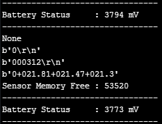
CMD - '?!' (Probe Address)
RES - '0'This works correctly
CMD - '02C' (Take Temp Reading)
RES - '000312' (1-4 is the time taken to read sensors 5-6 is the amount of sensors read)This doesn't show all readings
CMD - '0D0' (Show Temp Readings first 8 sensors)
RES - '0+028.12+027.24+027.03+026.78+026.65+025.45+023.34+021.21' (temp readings after each +0)
***Only some of the readings show I have never been able to get more then 6 show at a time.This doesn't seem to work yet
CMD - '0D1' (Show temp readings last 4 sensors)
RES - '0+028.12+027.24+027.03+026.78'Hopefully it is just a buffer size issue and the payload is not too large.
-
Updated, does this look correct?
With this I did manage to receive something although not correct I am getting closer
-
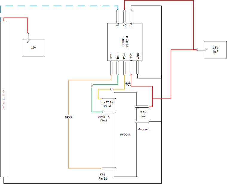
@jimpower RS485 is a symmetrical differential interface of at least +/- 200 mV The SDI-12 uses 5V logic levels, the xxPys a 3.3 V level. The RS485 is (mis-)used to create a half duplex interface AND to do the level transformation.
Looking at the data sheet It is now clear to me why the 1.8 V is needed. The max output level of the RS485 to the sensor is 3.3 V. To achieve 5V, the 1.8 V is added.
-
@robert-hh This could be an issue, only having 12v and 3.3v sources, I thought the RS-485 breakout could do 5v to 3.3v step down but not the other way. I may have to build a 12v to 5v step down circuit.
-
This post is deleted!
-
@robert-hh said in SDI-12 Soil Moisture Probe Help:
@jimpower connect the 1.8V source to A and the moisture sensor to B. RS485 is a current loop signal, so swapping the cables inverts the polarity.
This is how they are connected in the current state. A goes to 1.8V (which isn't a source just a Vref not sure if this should be 3.3v however) and B goes to the probe.
-
@jimpower connect the 1.8V source to A and the moisture sensor to B. RS485 is a differential signal, so swapping the cables inverts the polarity.
-
@robert-hh said in SDI-12 Soil Moisture Probe Help:
@jimpower The nopte about swapping A & B was with the RS485 breakout board, if the quiescent level at the xxPy RX is 0, when it should be 3.3V.
Could you help me to understand how i should do this?
-
@jimpower The nopte about swapping A & B was with the RS485 breakout board, if the quiescent level at the xxPy RX is 0, when it should be 3.3V.
-
@robert-hh "And some ground lines seem to be missing in your pictures." If you're referring to the A - 1.8V this is purely used as a reference from battery charge controller, I could run this back to the LoPy vref I guess. I didn't include the 12v and earth lines of the sensor but they are connected to a separate solar mppt controller.
As SDI-12 uses the one wire for TX & RX (B) I didn't think i could use a simple UART TTL I could try this but I'm not sure how to go about swapping between them. A is used as a reference only. I do think I may need to add a resistor in series between the RX and 3.3V, and should probably add a cap in series between RO and ground.
-
@jimpower Looking at the protocol, a simple 3.3 to 5 V level shifer should be enough to connect to the SDI-12 data line. You should connect it with a series resistor in TX, to copy with the half duplex property. That might be the reason for the RS485 adapter, which would allow an easier coupling. xxPy's do not support half duplex operation at the moment. Maybe it is also possible to switch the TX line after UART init to open drain. But that is to be tested.
For the actual device, you may maybe only have to exchange A and B at the breakout board. That should be required if the "silent" state at the RX side of the the xxPY is 0. And some ground lines seem to be missing in your pictures.