5V Relay on pycom
-
Hi all,
I have a pycom with the LoPy integrated.
I would like to push up a relay, but I don't know if what I'm doing is well.
I have a water pump motor joined to the relay. When I connect the pycom to my machine, I heard the relay sound noise, but nothing else.
I did it like this.p_relay = Pin('P11', mode=Pin.OUT, pull=Pin.PULL_UP) while True: p_relay.PULL_DOWN print("OFF for 2 seconds") time.sleep(2) p_relay.PULL_UP print("ON for 2 seconds") time.sleep(2)Is it a good sample for starting ? Do you have any other idea?
Note that I have a AC/DC adapter, how can I joined it to my relay?
-
@kebson Thinking about your message, I assume that you connected the collector of the transistor to GND and control the relay though through the Vcc & GND pins of that relay board. Two topics are to be discussed:
- Current draw. According to the data sheet, the coil resistance is 70 Ohm, resulting in an current of 47 mA at 3.3V. At that load, the output voltage should be lower than 3.3 V, so it might "just" fit. At about 3V, the force at the relay contacts may be lower than at 5V, causing higher relay contact wear.
- Flyback voltage peaks. If you did not remove the flyback diode from the board, that might work, at least for a while.
But still I would not consider to connect an inductive load directly to the ESP32 output pins. It may work for a while, but then break.
B.T.W.: What is the mains voltage/power of the Pump?
-
@robert-hh It works, I just remove the transistor, and let the 3V3 to control the relay.
I saw in a website if You directly connect a 5v relay in a 3V3, without transistor, you'll fry the pycom.
But I tried it yesterday, and it works well.
Thank you
-
@robert-hh yes, and it's my water pomp I will switch with. But for now, I just would like to see its turns on and off. Because it doesn't. I'm using a transistor P2N2222 to try with it now.
-
@kebson What do you expect from a relay? It is just a solenoid operated switch. When it turns on, you hear a sharp click, it if turns off, you'll hear a soft click. In order to tell if it is working, you have to switch something with it.
-
@robert-hh It's what i did, but like i said, I just heard a sound, and see the LED turns on, but nothing else.
My relay if it will work, I would like to connect it to a water pump. So, if I can't have the steps on turns on and off the relay, I couldn't continue.
-
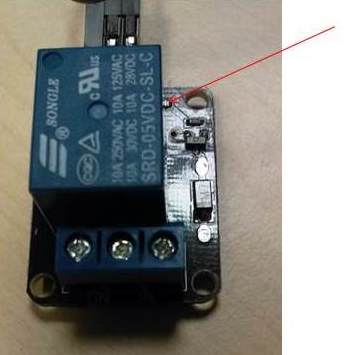
@kebson Red is ok. That has a drop voltage of about 1.4 V, and should work with 3.3 V input voltage. The Vcc input at the board should be 5V, if the device is connected to USB. You could try to bypass the LED and connect the P11 output to the point indicated by the arrow in the picture below.
-
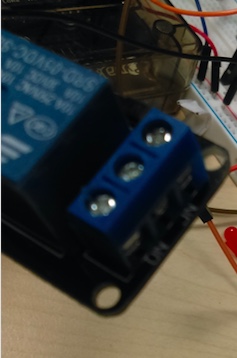
@robert-hh I edited my last answer and put RED color. The relay VCC is connected to my first pin (Vin (3.5-5.5V)).
-
@kebson Is the relay Vcc connected to 5V or 3.3V? And again, what is the color of the LED? Red or green or yellow or blue? It is important, because from the color I can tell the voltage dop of the LED.
-
@robert-hh Yeah, when I connect the pycom on the machine, the LED turns on in RED color and I heard a little sound. But he does it once in two.
-
@kebson Thanks. Did you ever see the LED turning on. And if yes, what's the color?
-
-
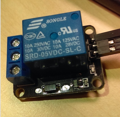
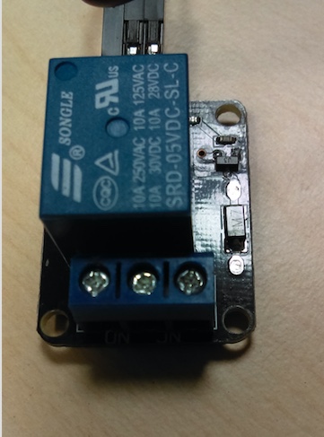
@kebson Can you post an as-good-as-possible picture of the upper and lower side of the relay board. The upper side should show the transistor and the LED. Then I can derive the schematics.
-
@robert-hh YEah I commentend the second line, but yes, I would like to put the relay on when result_dht returns True. and turn it off otherwise.
Yesterday, I joined the relay with a transistor, a resistance, but nothing happened. That's why, i disconnect the transistor, and now, it's directly connected on the 3V3 pycom.
-
@kebson I do not understand why you have that:
p_relay.value(1)
p_relay.value(0)
at the beginning, because that gives just a 3µs pulse at the output. Besides that I assume, that you want to switch the relay on, when result_dht.is_valid() returns True.
If you have a voltmeter, you should see output P11 change it's level. If it does, the program logic is OK, but the relay board does not switch with 3.3 V.
-
@robert-hh I try what you said but, nothing special
p_relay = Pin('P11', mode=Pin.OUT)
p_relay.value(1)
p_relay.value(0)
while True:
   if result_dht.is_valid():
        p_relay(1)
   else:
        p_relay(0)
Is there something wrong in the code?
-
@robert-hh Ok I will try it in a few minutes to see.
-
@kebson The picture in the link shows a transistor and and a flyback diode on the board. And the text tells about 3.3 and 5V compatibility.
The in the code above, to swich the output, you have to issue:
p_relay.value(1)
and
p_relay-value(0)
to switch the output to high and low. You may also write:
p_relay(1) and p_relay(0).
-
Thanks for the response,
My relay is like this.Yeah I heard I must have a transistor, but when I connect it, nothing happens, and if I deconnect if, I heard the relay noise.
@robert-hh @timh @Eric73
-
@Kebson
I'm not sure about pycom lexical, but in electronics, pull-up and pull-down is used for input pin only (not push-pull output as you configure your pin). If you want to drive your relay with a low value on your pin use "p_relay.value(0)" and "p_relay.value(1)".
Please note that if you have directly connected your solenoid to the output of your device it's insane and will not work (even you can destroy your pycom device if you haven't a free wheel diode) (output pin of pycom device cannot source more than few milli amp, and can sink about 10mA max). You must use a transistor NPN or fet to drive more current as robert-hh said.