Connecting FiPy to sensor
-
I have FiPy mounted on Expansion Board 3.0 and the latter connected. to PC with USB-to-miniUSB cable. I also have a sensor that has PH-2.0-3P connector where pins are: GND, 5V INPUT, and VCC OUTPUT.
- What pin on the Expansion Board should I connect with sensor VCC ?
- Where do I get 5V to feed the 5V INPUT pin on the sensor? Expansion Board output has 3.3V so how do I convert it to 5V to feed the sensor?
- Do I connect sensor GND pin to GND pin on Expansio Board?
I also have breadboard and the wires...
EDIT:
- I will not be using the breadboard - the Expansion Board is sufficient.
- I notice that I have Expansion Board 3.1 and the pinout of my board is different from the one in Pycom documentation, which refers to 3.0 . [Pycom, really? Where is the documentation/pinout for 3.1? How can you release 3.1 and not even mention anywhere that the pinout is different from 3.0 documentation?]
- So to clarify my original question (what pin on the Expansion Board 3.1 I connect the analog output pin from the sensor) - I am attaching the picture here:
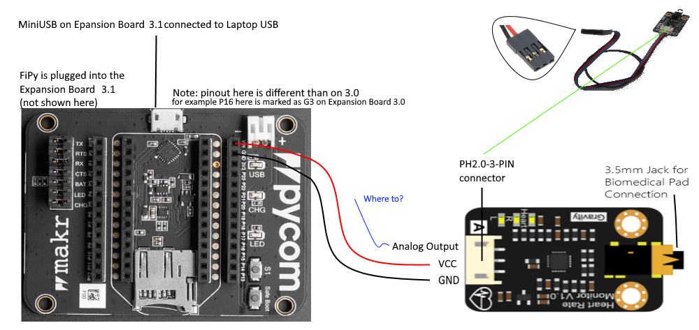
-
@securigy The pinout for the expansion board 2 shows the G-numbers and some P-numbers. Since the P-numbers are increasing along the sides, you can fill the gaps.
https://docs.pycom.io/gitbook/assets/expansion2-pinout.pdf
-
@robert-hh thank you Robert. I will try your suggestion. Also where do I find "translation" between G and P pin notation?
-
@securigy If it is an analog output, you have to use an analog input, like G5, G4, G31 or G30 (P13, P14, P17, P18). G3 aka P16 is connected to the battery connector of the board, G0 aka P15 to the LTE modem. Take care to set the range of the ADC accordingly.
-
@robert-hh Got it. Thanks. I was slowly coming to the same conclusion...
What pin on on the Expansion Board do I connect the Analog Output from the sensor? Is G7 or G8 will do?
-
@securigy You have to connect GND to GND. The Vin Pin on the Expansion Board carries 5V when the device is supplied by USB. So you can connect Vin to 5V Input of the sensor. That's it for supply. You need then make additional connections for the sensor's data signals.
Do NOT connect 3.3V of the expansion board to the Vcc output of the sensor. That might damage the Fipy.