How to read out the output of 'ezPyro SMD I2C Pyroelectric Infrared Sensor' via I2C command?
-
Hi There,
I'm a newbie in the micro-controller world. I have started with Pycom Expansion board and LoPY4.
I have been reading the docs from the Pycom website and trying to understand how to 'Talk' to a connected sensor.
I have a little bit of experience with micro-controller & sensor stuffs but it was on PIC18 and the language was C. Python is something new for me, still I'm trying to learn how to program and make it work on Pycom.
So far what I have understood about I2C communication is, I'll have to create the I2C object and initialize it with Pins and Type i.e. Master. Then I will have to set the sensor's I2C address from where the output of the sensor would be read. And then I can assign this value to a variable and get it printed. Below is the code I got from the Pycom website and I rearranged it as below:from machine import I2C i2c = I2C(0, I2C.MASTER, baudrate=100000) value=i2c.readfrom(address of the sensor's I2C,) print ("value")Is it that simple or I'm just totally wrong?
The sensor I'm using is a gas sensor. The sensor's output is current. I need to measure that current value to convert it into another measurement. The datasheet exceeds the maximum upload limit. Hence, I have inserted the images of the I2C section below for the reference.
So please guide and enlighten me how can I get it done. Your help is much appreciated.Regards
-
@Oridroo said in How to read out the output of 'ezPyro SMD I2C Pyroelectric Infrared Sensor' via I2C command?:
Would you please explain a bit how you did this calculation, like why you divided it by 4 and then right shifted?
No, not and but OR, shift a binary number to left is equal to multiply this number by 2, shift a binary number to rigth is equal to divide this number by 2. This work for all power of 2 value.
My question is, why we are shifting the bits to get the decimal value?
Your sensor compute a value between 0 and (2^24-1), then we need to transfer this value by i2c bus, but i2c bus can only transport bytes by bytes. So manufacturer say in datasheet the sensors send the on i2c 3 bytes, the first byte is [23..16] bits of this number, the next is [15..8] bits of this value and the last is [7..0] of this value. So we have a byte array[3] of 8 bit after reading on i2c. To compute this in decimal we have to shift the first byte of array by 16 bits (or multiply by 65536 it's same result), the second byte as to be shifted by 8 bits (or multiply by 256 it's same result) and the last byte is added to the value.
For the time being, my current working code is as below. I was getting continuous "OSError: I2C bus error" until I added one delay in between print("Analogue:", analog) & ana_sett = i2c.writeto_mem(0x65, 0x14, analog)
The code was executing till printing 'Analogue' and then showing that I2C error. Please suggest me if you have any recommendation for the programme.No idea why you have this, but for me it's mean that the sensors doesn't be ready to anwser to the command.
You can use smaller delay if you use time.sleep(0.1) you have 100 ms delay
-
@Eric73 , Once again, Thanks a lot for the explanation.
My Wipy's firmware is:
Firmware: (sysname='WiPy', nodename='WiPy', release='1.20.0.rc13', version='v1.9.4-94bb382 on 2019-08-22', machine='WiPy with ESP32')
Would you please explain a bit how you did this calculation, like why you divided it by 4 and then right shifted?
"0x29/4 == 0xA the fifo clear command (x/4 == x>>2) , 0x29 & 0x3==1 so answer is command ok"
Actually I tried to read a bit about bit shifting but couldn't fully understand how it is happening to convert the binary to decimal (in the code below).
What I understood is, Left bit shifting is like multiplying by 2 and right bit shifting is division by 2. As we shifted to left by 16 and 8 bits respectively, those two bytes got multiplied by 2^16 (65536) & 2^8 (256) respectively. And we didn't shift the last bit, hence 2^0 = 1.
My question is, why we are shifting the bits to get the decimal value?
Ch1_value=fifo_read_active[3]*65536+fifo_read_active[4]*256+fifo_read_active[5]For the time being, my current working code is as below. I was getting continuous "OSError: I2C bus error" until I added one delay in between print("Analogue:", analog) & ana_sett = i2c.writeto_mem(0x65, 0x14, analog)
The code was executing till printing 'Analogue' and then showing that I2C error. Please suggest me if you have any recommendation for the programme.
Regardsfrom machine import I2C, Timer import time import ubinascii import os print("Firmware:",os.uname()) i2c = I2C(0, I2C.MASTER) i2c = I2C(0, pins=('P10','P9')) print("I2C Address", i2c.scan()) wake_up = i2c.readfrom_mem(0x65, 0x22, 1) print("Wake_UP:", wake_up) time.sleep(1) FIFO_status = i2c.readfrom_mem(0x65, 0x04, 1) print("FIFO_Status:", FIFO_status) time.sleep(1) buf = bytes([0x00, 0x07, 0x07, 0x07, 0x07]) print("Buffer:", buf) chnl_ctr = i2c.writeto_mem(0x65, 0x10, buf) print("Channel Control:", chnl_ctr) time.sleep(1) analog = bytes([0x00, 0x09]) print("Analogue:", analog) time.sleep(1) ana_sett = i2c.writeto_mem(0x65, 0x14, analog) print("Analog Settings:", ana_sett) time.sleep(1) ana_read = i2c.readfrom_mem(0x65, 0x12, 4) print("Analog Read:", ana_read) time.sleep(1) fifo_read_active = i2c.readfrom_mem(0x65, 0x08, 17) print("fifo_read_active:", fifo_read_active) hex = ubinascii.hexlify(fifo_read_active) print("FIFO_Read_Active_Chnl:",hex) time.sleep(1) # fifo_read_full = i2c.readfrom_mem(0x65, 0x06, 17) # print("FIFO_Read_All_Chnl:", fifo_read_full) # frame_count_MSB = fifo_read_active[15] # frame_count_LSB = fifo_read_active[16] #print("Frame Count MSB:", frame_count_MSB) #print("Frame Count LSB:", frame_count_LSB) #print("Individual Channel Bytes: 3, 4, 5, 6, 7, 8 :--- ",fifo_read_active[3],fifo_read_active[4],fifo_read_active[5],fifo_read_active[6],fifo_read_active[7],fifo_read_active[8] ) #print("Individual Channel Bytes: 9,10,11,12,13,14,15,16 :--- ",fifo_read_active[9],fifo_read_active[10],fifo_read_active[11],fifo_read_active[12],fifo_read_active[13],fifo_read_active[14],fifo_read_active[15],fifo_read_active[16] ) USB = fifo_read_active[3] MSB = fifo_read_active[4] LSB = fifo_read_active[5] Ch1_value=fifo_read_active[3]*65536+fifo_read_active[4]*256+fifo_read_active[5] Ch1_value=Ch1_value/1000 print("Channel_1:", Ch1_value) # Ch1_value_BS=((USB<<16) + (MSB<<8) + LSB) #Using bit shifting to convert binary to decimal # print("Channel_1_BS:", Ch1_value_BS) Ch2_value=fifo_read_active[6]*65536+fifo_read_active[7]*256+fifo_read_active[8] Ch2_value=Ch2_value/1000 print("Channel_2:", Ch2_value) Ch3_value=fifo_read_active[9]*65536+fifo_read_active[10]*256+fifo_read_active[11] Ch3_value=Ch3_value/1000 print("Channel_3:", Ch3_value) Ch4_value=fifo_read_active[12]*65536+fifo_read_active[13]*256+fifo_read_active[14] Ch4_value=Ch4_value/1000 print("Channel_4:", Ch4_value) FIFO_clear = i2c.readfrom_mem(0x65, 0x0A, 1) print("FIFO_Clear:", FIFO_clear) time.sleep(1) FIFO_reset = i2c.readfrom_mem(0x65, 0x0C, 1) print("FIFO_Reset:", FIFO_reset) time.sleep(1) FIFO_status = i2c.readfrom_mem(0x65, 0x04, 1) print("FIFO_Status:", FIFO_status) time.sleep(1)Output:
>>>
>>>
Firmware: (sysname='WiPy', nodename='WiPy', release='1.20.0.rc13', version='v1.9.4-94bb382 on 2019-08-22', machine='WiPy with ESP32')
I2C Address [101]
Wake_UP: b'\x89'
FIFO_Status: b'='
Buffer: b'\x00\x07\x07\x07\x07'
Channel Control: 5
Analogue: b'\x00\t'
Analog Settings: 2
Analog Read: b'\x00\t\t\t'
fifo_read_active: b'\x00\x1e2\x00!\xad\x00 \x83\x00#\x113\xd23\xd23'
FIFO_Read_Active_Chnl: b'001e320021ad00208300231133d233d233'
Channel_1: 8.621
Channel_2: 8.323
Channel_3: 8.977
Channel_4: 3396.147
FIFO_Clear: b')'
FIFO_Reset: b'1'
FIFO_Status: b'='
>
Pycom MicroPython 1.20.0.rc13 [v1.9.4-94bb382] on 2019-08-22; WiPy with ESP32
Type "help()" for more information.
-
@Oridroo said in How to read out the output of 'ezPyro SMD I2C Pyroelectric Infrared Sensor' via I2C command?:
b')' and b'='
Look at hex value of this character, 0x29 and 0x3D
0x29/4 == 0xA the fifo clear command (x/4 == x>>2) , 0x29 & 0x3==1 so answer is command ok as explain in DS 13.3, if 0x29 &0x3==2 it's mean command failed.(& sign is AND boolean bit operator)
0x3D is answer to fifo status (as DS 13.3.3 ) in binary 00111101
WakeDetect :0
Error0 and 1 : 01 (read when fifo empty or write when fifo full)
FifoCount : 1110 so 14 data packet is present in memoryYou can do a fifo_reset to clear all fifo value, and then read fresh value after waiting some time.
About the value read i have no idea what the sensor value mean or if it's a normal or anormal result, sorry i have no technical knowledge about this. The sensor manufacturer is better to answer about this.
It seem (but i am not sure) that channel 4 and frame count is WRONG VALUE, Error0 and Error1 seem show that the host (your pycom device are you using the latest firmware ? ) have aborted the read (not read the 17 byte as requested).
I SUGGEST : Add pull-up on i2c line AND/OR try low baudrate for testing this
i2c = I2C(0, I2C.MASTER,pins=('P10','P9'),baudrate=20000)
-
Hi @Eric73 , Thanks a lot for your guidelines. I am getting some outputs now, although not so sure how accurate they are. Below is the code I'm using now. I tried to use FIFO_Clear and FIFO_Status commands but none of them worked. I sent the command same as Wake-Up command but getting b')' and b'=' as output!
I tried to Frame Count (MSB & LSB) command as well and getting some outputs although not so sure what do they indicate?
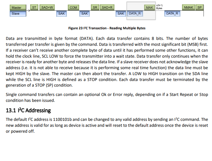
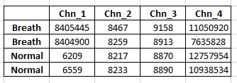
Another thing is, out of 4 active channels, the output of Channel_2 and Channel_3 is more or less same for every execution (~8000-9000). On the other hand, Channel_1's output varies in the range of 5000~12000 in normal condition (sensor kept in open air inside the room). But if I blow my breath around it, the value becomes way higher. And Channel_4's output is something always high in most of the cases. Please see the image below. So, I'm wondering how accurate are they. As I'm getting change in channel_1, so I'm thinking of taking it as standard/reference to calculate the change in gas ppm. Please share your valuable opinion.
from machine import I2C, Timer
import time
import ubinascii

i2c = I2C(0, I2C.MASTER)
i2c = I2C(0, pins=('P10','P9'))
print("I2C Address", i2c.scan())

wake_up = i2c.readfrom_mem(0x65, 0x22, 1)
print("Wake_UP:", wake_up)
time.sleep(1)

FIFO_status = i2c.readfrom_mem(0x65, 0x04, 1)
print("FIFO_Status:", FIFO_status)
time.sleep(1)

buf = bytes([0x00, 0x07, 0x07, 0x07, 0x07])
print("Buffer:", buf)

chnl_ctr = i2c.writeto_mem(0x65, 0x10, buf)
print("Channel Control:", chnl_ctr)
time.sleep(1)

analog = bytes([0x00, 0x09])
print("Analogue:", analog)
ana_sett = i2c.writeto_mem(0x65, 0x14, analog)
print("Analog Settings:", ana_sett)
time.sleep(2)
ana_read = i2c.readfrom_mem(0x65, 0x12, 4)
print("Analog Read:", ana_read)
time.sleep(2)


fifo_read_active = i2c.readfrom_mem(0x65, 0x08, 17)
print("fifo_read_active:", fifo_read_active)
hex = ubinascii.hexlify(fifo_read_active)
print("FIFO_Read_Active_Chnl:",hex)
time.sleep(1)
fifo_read_full = i2c.readfrom_mem(0x65, 0x06, 17)
print("FIFO_Read_All_Chnl:", fifo_read_full)

frame_count_MSB = fifo_read_active[15]
frame_count_LSB = fifo_read_active[16]

print("Frame Count MSB:", frame_count_MSB)
print("Frame Count LSB:", frame_count_LSB)

print("Individual Channel Bytes: 3, 4, 5, 6, 7, 8 :--- ",fifo_read_active[3],fifo_read_active[4],fifo_read_active[5],fifo_read_active[6],fifo_read_active[7],fifo_read_active[8] )

print("Individual Channel Bytes: 9,10,11,12,13,14,15,16 :--- ",fifo_read_active[9],fifo_read_active[10],fifo_read_active[11],fifo_read_active[12],fifo_read_active[13],fifo_read_active[14],fifo_read_active[15],fifo_read_active[16] )

USB = fifo_read_active[3]
MSB = fifo_read_active[4]
LSB = fifo_read_active[5]
Ch1_value=fifo_read_active[3]*65536+fifo_read_active[4]*256+fifo_read_active[5]
print("Channel_1:", Ch1_value)

Ch1_value_BS=((USB<<16) + (MSB<<8) + LSB)
print("Channel_1_BS:", Ch1_value_BS)

Ch2_value=fifo_read_active[6]*65536+fifo_read_active[7]*256+fifo_read_active[8]
print("Channel_2:", Ch2_value)

Ch3_value=fifo_read_active[9]*65536+fifo_read_active[10]*256+fifo_read_active[11]
print("Channel_3:", Ch3_value)

Ch4_value=fifo_read_active[12]*65536+fifo_read_active[13]*256+fifo_read_active[14]
print("Channel_4:", Ch4_value)

FIFO_clear = i2c.readfrom_mem(0x65, 0x0A, 1)
print("FIFO_Clear:", FIFO_clear)
time.sleep(1)

FIFO_status = i2c.readfrom_mem(0x65, 0x04, 1)
print("FIFO_Status:", FIFO_status)
time.sleep(1)
Output
I2C Address [101]
Wake_UP: b'\x89'
FIFO_Status: b'='
Buffer: b'\x00\x07\x07\x07\x07'
Channel Control: 5
Analogue: b'\x00\t'
Analog Settings: 2
Analog Read: b'\x00\t\t\t'
fifo_read_active: b'\x00\x1d\xbf\x000z\x00 5\x00"\xdd\xe9\x83\xe9\x83\xe9'
FIFO_Read_Active_Chnl: b'001dbf00307a0020350022dde983e983e9'
FIFO_Read_All_Chnl: b'\x00\x1d\xbf\x000z\x00 5\x00"\xdd\xe9\x83\xe9\x83\xe9'
Frame Count MSB: 131
Frame Count LSB: 233
Individual Channel Bytes: 3, 4, 5, 6, 7, 8 :---  0 48 122 0 32 53
Individual Channel Bytes: 9,10,11,12,13,14,15,16 :---  0 34 221 233 131 233 131 233
Channel_1: 12410
Channel_1_BS: 12410
Channel_2: 8245
Channel_3: 8925
Channel_4: 15303657
FIFO_Clear: b')'
FIFO_Status: b'='
Regards
-
Here, [3], [4], [5] which array they are indicating?
Well, it's from your code
fifo_read_active = i2c.readfrom_mem(0x65, 0x08, 17)i2c.readfrom return a bytes array that contain the bytes read on i2c bus. So index [0,1,2] is for channel 0 and index [3,4,5] is for channel 1 as explain in DS 13.3.10 (and so on)
And can you please show me how would I convert thw FIFO output byte into Decimal in micropython? I found few examples for python but didn't workout.
That's exactly what this line do
ValCh1=fifo_read_active[3]*65536+fifo_read_active[4]*256+fifo_read_active[5]So you have to compute ValCh2 with 6,7,8 and so on for all channel
-
@Eric73 here is the rest of the code:
/*********************************************************************************
 * Channel Control Packet (CCP) Modification
 *********************************************************************************/
    if (keyboard_buffer == "PX1") {                   // Single Pixel Sensor
      ezPyro_Pixel = 1;
      Read_CCP();                                     // Read the CCP
      set_CCP();
      Write_CCP();                                    // Write CCP
      Serial.println(F("Single Pixel Sensor Set"));
      Read_CCP();                                     // Read the CCP
    }

    if (keyboard_buffer == "PX4") {                   // 2x2 Pixel Sensor
      ezPyro_Pixel = 4;
      Read_CCP();                                     // Read the CCP
      set_CCP();
      Write_CCP();                                    // Write CCP
      Serial.println(F("2x2 Pixel Sensor Set"));
      Read_CCP();                                     // Read the CCP
    }

    if (keyboard_buffer == "HPF1") {                  // HPF Freq= 1Hz
      Read_CCP();                                     // Read the CCP
      ezPyro_FIFO[2] = ezPyro_FIFO[2] & 0xCF;         // &1100 1111 clr HPF
      ezPyro_FIFO[2] = ezPyro_FIFO[2] | ezPyro_CCP_HP_FILTER_1 ;
      set_CCP();
      Write_CCP();                                    // Write CCP
      Serial.println(F("High Pass Frequency Filter set to 1Hz"));
      Read_CCP();                                     // Read the CCP
    }

    if (keyboard_buffer == "HPF2") {                  // HPF Freq= 2Hz
      Read_CCP();                                     // Read the CCP
      ezPyro_FIFO[2] = ezPyro_FIFO[2] & 0xCF;         // &1100 1111 clr HPF Freq
      ezPyro_FIFO[2] = ezPyro_FIFO[2] | ezPyro_CCP_HP_FILTER_2 ;
      set_CCP();
      Write_CCP();                                    // Write CCP
      Serial.println(F("High Pass Frequency Filter set to 2Hz"));
      Read_CCP();                                     // Read the CCP
    }

    if (keyboard_buffer == "HPF4") {                  // HPF Freq= 4Hz
      Read_CCP();                                     // Read the CCP
      ezPyro_FIFO[2] = ezPyro_FIFO[2] & 0xCF;         // &1100 1111 clr HPF Freq
      ezPyro_FIFO[2] = ezPyro_FIFO[2] | ezPyro_CCP_HP_FILTER_4 ;
      set_CCP();
      Write_CCP();                                    // Write CCP
      Serial.println(F("High Pass Frequency Filter set to 4Hz"));
      Read_CCP();                                     // Read the CCP
    }

    if (keyboard_buffer == "HPF8") {                  // HPF Freq= 8Hz
      Read_CCP();                                     // Read the CCP
      ezPyro_FIFO[2] = ezPyro_FIFO[2] & 0xCF;         // &1100 1111 clr HPF Freq
      ezPyro_FIFO[2] = ezPyro_FIFO[2] | ezPyro_CCP_HP_FILTER_8 ;
      set_CCP();
      Write_CCP();                                    // Write CCP
      Serial.println(F("High Pass Frequency Filter set to 8Hz"));
      Read_CCP();                                     // Read the CCP
    }

    if (keyboard_buffer == "T120") {                  // Transconductance = 1.2T
      Read_CCP();                                     // Read the CCP
      ezPyro_FIFO[2] = ezPyro_FIFO[2] & 0x3F;         // &0011 1111 clr Transcnd
      ezPyro_FIFO[2] = ezPyro_FIFO[2] | ezPyro_CCP_TRANS_120T ;
      set_CCP();
      Write_CCP();                                    // Write CCP
      Serial.println(F("Transconductance set to 1.2T"));
      Read_CCP();                                     // Read the CCP
    }                                                 // End If T120

    if (keyboard_buffer == "T060") {                  // Transconductance = 0.6T
      Read_CCP();                                     // Read the CCP
      ezPyro_FIFO[2] = ezPyro_FIFO[2] & 0x3F;         // &0011 1111 clr Transcnd
      ezPyro_FIFO[2] = ezPyro_FIFO[2] | ezPyro_CCP_TRANS_060T ;
      set_CCP();
      Write_CCP();                                    // Write CCP
      Serial.println(F("Transconductance set to 0.6T"));
      Read_CCP();                                     // Read the CCP
    }                                                 // End If T060

    if (keyboard_buffer == "T030") {                  // Transconductance = 0.3T
      Read_CCP();                                     // Read the CCP
      ezPyro_FIFO[2] = ezPyro_FIFO[2] & 0x3F;         // &0011 1111 clr Transcnd
      ezPyro_FIFO[2] = ezPyro_FIFO[2] | ezPyro_CCP_TRANS_030T ;
      set_CCP();
      Write_CCP();                                    // Write CCP
      Serial.println(F("Transconductance set to 0.3T"));
      Read_CCP();                                     // Read the CCP
    }                                                 // End If T030

    if (keyboard_buffer == "T015") {                  // Transconductance = 0.15T
      Read_CCP();                                     // Read the CCP
      ezPyro_FIFO[2] = ezPyro_FIFO[2] & 0x3F;         // &0011 1111 clr Transcnd
      ezPyro_FIFO[2] = ezPyro_FIFO[2] | ezPyro_CCP_TRANS_015T ;
      set_CCP();
      Write_CCP();                                    // Write CCP
      Serial.println(F("Transconductance set to 0.15T"));
      Read_CCP();                                     // Read the CCP
    }                                                 // End If T015

    if (keyboard_buffer == "X1"){                     // Amplification = 1x
      Read_CCP();                                     // Read the CCP
      ezPyro_FIFO[2] = ezPyro_FIFO[2] & 0xF1;         // &1111 0001 clr Amp
      ezPyro_FIFO[2] = ezPyro_FIFO[2] | ezPyro_CCP_AMP_01x ;
      set_CCP();
      Write_CCP();                                    // Write CCP
      Serial.println(F("Amplification set to 1x"));
      Read_CCP();                                     // Read the CCP
    }                                                 // End If X1

    if (keyboard_buffer == "X2"){                     // Amplification = 2x
      Read_CCP();                                    // Read the CCP
      ezPyro_FIFO[2] = ezPyro_FIFO[2] & 0xF1;        // &1111 0001 clr Amp
      ezPyro_FIFO[2] = ezPyro_FIFO[2] | ezPyro_CCP_AMP_02x ;
      set_CCP();
      Write_CCP();                                   // Write CCP
      Serial.println(F("Amplification set to 2x"));
      Read_CCP();                                    // Read the CCP
    }                                                // End If X2

    if (keyboard_buffer == "X4"){                    // Amplification = 4x
      Read_CCP();                                    // Read the CCP
      ezPyro_FIFO[2] = ezPyro_FIFO[2] & 0xF1;        // &1111 0001 clr Amp
      ezPyro_FIFO[2] = ezPyro_FIFO[2] | ezPyro_CCP_AMP_04x ;
      set_CCP();
      Write_CCP();                                   // Write CCP
      Serial.println(F("Amplification set to 4x"));
      Read_CCP();                                    // Read the CCP
    }                                                // End If X4

    if (keyboard_buffer == "X8"){                    // Amplification = 8x
      Read_CCP();                                    // Read the CCP
      ezPyro_FIFO[2] = ezPyro_FIFO[2] & 0xF1;        // &1111 0001 clr Amp
      ezPyro_FIFO[2] = ezPyro_FIFO[2] | ezPyro_CCP_AMP_08x ;
      set_CCP();
      Write_CCP();                                   // Write CCP
      Serial.println(F("Amplification set to 8x"));
      Read_CCP();                                    // Read the CCP
    }                                                // End If X8

    if (keyboard_buffer == "X16"){                    // Amplification = 16x
      Read_CCP();                                    // Read the CCP
      ezPyro_FIFO[2] = ezPyro_FIFO[2] & 0xF1;        // &1111 0001 clr Amp
      ezPyro_FIFO[2] = ezPyro_FIFO[2] | ezPyro_CCP_AMP_16x ;
      set_CCP();
      Write_CCP();                                   // Write CCP
      Serial.println(F("Amplification set to 16x"));
      Read_CCP();                                    // Read the CCP
    }                                                // End If X16

    if (keyboard_buffer == "X32"){                    // Amplification = 32x
      Read_CCP();                                     // Read the CCP
      ezPyro_FIFO[2] = ezPyro_FIFO[2] & 0xF1;         // &1111 0001 clr Amp
      ezPyro_FIFO[2] = ezPyro_FIFO[2] | ezPyro_CCP_AMP_32x ;
      set_CCP();
      Write_CCP();                                    // Write CCP
      Serial.println(F("Amplification set to 32x"));
      Read_CCP();                                     // Read the CCP
    }                                                 // End If X32

    if (keyboard_buffer == "X64"){                    // Amplification = 64x
      Read_CCP();                                     // Read the CCP
      ezPyro_FIFO[2] = ezPyro_FIFO[2] & 0xF1;        // &1111 0001 clr Amp
      ezPyro_FIFO[2] = ezPyro_FIFO[2] | ezPyro_CCP_AMP_64x;
      set_CCP();
      Write_CCP();                                   // Write CCP
      Serial.println(F("Amplification set to 64x"));
      Read_CCP();                                    // Read the CCP
    }                                                // End If X64
  }
  keyboard_buffer ="";
} // End Serial Port Read

/*********************************************************************************
 * Start_ASIC function
 * Setup & Start the ASIC
**********************************************************************************/
void Start_ASIC(void) {
  Wire.begin();                                                 // Start up the Soft i2c bus
  Wire.beginTransmission(ezPyro_i2c);                           // Check the device is on the i2C bus at 0x65
  error = Wire.endTransmission();
  Serial.println();
  Serial.print(F("Tx simple toggle : "));
  check_error();

  if (!readI2C(ezPyro_i2c, ezPyro_VERSION, 1)) {                // Read the chip Version
    Serial.println(F("Read Version Error"));
    while (1);
  }
  Serial.print(F("ASIC Version = , "));
  Serial.println(ezPyro_FIFO[0]);

  // ***** Write the Analog Front End Packet
  // Byte 0 is the Sampling Rate. Sample Rate = 1000 / (N + 1)
  // N =   0, Rate = 1000.00
  // N =   1, Rate =  500.00
  // :
  // N = 255, Rate =    3.92
  //
  // Note that when you use this, the number of readings (N+1) get added together
  // so the full 23 bits of the data packet get used ...
  ezPyro_Clock_Divider = 10;
  ezPyro_FIFO[0] = (ezPyro_Clock_Divider - 1);
  // Set AFE Byte 1
  ezPyro_FIFO[1] = ezPyro_INT_ENABLE;                           // En Interrupts
  ezPyro_FIFO[1] |= ezPyro_TEMP_ENABLE;                         // En Temp Monitor
  ezPyro_FIFO[1] |= ezPyro_LO_PASS_FREQ_022_5;                  // LPF
  ezPyro_FIFO[1] |= ezPyro_HI_PASS_FILTER_ON;                   // HPF on
  //ezPyro_FIFO[1] |= ezPyro_LOW_POWER_MODE;                    // Low Power Mode

  Write_AFE();                                                  // Write AFE
  Read_AFE();                                                   // Read AFE

  // ***** Write the Channel Control Packet
  // Set up CCP
  // Activate Channel 2
  ezPyro_FIFO[2] |= ezPyro_CCP_ACTIVE ;
  ezPyro_FIFO[2] |= ezPyro_CCP_TRANS_015T;                      // Transcond 0.15T
  ezPyro_FIFO[2] |= ezPyro_CCP_HP_FILTER_8;                     // Set HPF to 8 Hz

  if(ezPyro_Pixel == 1){
    ezPyro_FIFO[2] |= ezPyro_CCP_AMP_01x ;                      // Fb Cap 3200= 1x Amp
    ezPyro_FIFO[0] = ezPyro_FIFO[2];                            // Ch0 is temp- Activate ch
  } else{
    ezPyro_FIFO[2] |= ezPyro_CCP_AMP_16x ;
    ezPyro_FIFO[0] = ezPyro_FIFO[2];                            // Ch0 is temp- Activate ch
    ezPyro_FIFO[1] = ezPyro_FIFO[2];                            // Channel 1 Activated
    ezPyro_FIFO[3] = ezPyro_FIFO[2];                            // Channel 3 Activated
    ezPyro_FIFO[4] = ezPyro_FIFO[2];                            // Channel 4 Activated
  }

  set_CCP();
  Write_CCP();                                                  // Write CCP
  Read_CCP();                                                   // Read CCP

  ezPyro_FIFO[0] = 0x65 << 1;                                   // Shift 7 LSB to 7 MSB
  if (!writeI2C(ezPyro_i2c, ezPyro_ADDR_WRITE, 1)) {            // Change the Address
    Serial.println(F("Write Set Addr Error"));
    while (1);
  }

  Serial.print(F("Addr Written = 0x"));
  ezPyro_i2c = ezPyro_FIFO[0] >> 1;                             // Shift 7 MSB to 7 LSB
  Serial.println(ezPyro_i2c, HEX);

  if (!writeI2C(ezPyro_i2c, ezPyro_FIFO_RESET, 0)) {            // Reset the full FIFO
    Serial.println(F("Reset FIFO Error"));
    while (1);
  }
  Serial.println();
}

/*********************************************************************************
 * readI2C function
 * Standard READ routine
 *********************************************************************************/
boolean readI2C(byte addr, byte command, byte data_count) {

  Wire.beginTransmission(addr);
  Wire.write(command);
  if (Wire.endTransmission(false) != 0) return false;
  Wire.requestFrom(ezPyro_i2c, data_count);
  for (i = 0 ; i < data_count ; i++){
    ezPyro_FIFO[i] = Wire.read();
  }
  return true;
} // End of Read I2C

/*********************************************************************************
 * function
 * Standard WRITE routine
 *********************************************************************************/
boolean writeI2C(byte addr, byte command, byte data_count) {
  Wire.beginTransmission(addr);
  Wire.write(command);
  for (i = 0 ; i < data_count ; i++){
    Wire.write(ezPyro_FIFO[i]);
  }
  return true;
} // End of Write I2C

/*********************************************************************************
 * function
 * Put the AFE to screen
 *********************************************************************************/
void display_AFE(){
  Serial.print(F("AFE ="));
  for (i = 0 ; i < 2 ; i++){
    Serial.print(F(" , "));
    Serial.print(ezPyro_FIFO[i]);
  }
  Serial.println();
} // End of Display AFE

/*********************************************************************************
 * function
 * Put the CCP to screen
 *********************************************************************************/
void display_CCP(){
  Serial.print(F("CCP ="));
  for (i = 0 ; i < 5 ; i++){
    Serial.print(F(" , "));
    Serial.print(ezPyro_FIFO[i]);
  }
  Serial.println();
} // End of Display CCP

/*********************************************************************************
 * set_CCP function
 * Set the CCP depending on single or 2x2 sensor
 * Activate Channel 1 , 2, 3 , 4 (4-pixel device)
 *********************************************************************************/
void set_CCP(){
  ezPyro_FIFO[0] = ezPyro_FIFO[2] ;
  ezPyro_FIFO[1] = ezPyro_FIFO[2] ;
  ezPyro_FIFO[3] = ezPyro_FIFO[2] ;
  ezPyro_FIFO[4] = ezPyro_FIFO[2] ;

  if(ezPyro_Pixel != 4){
    ezPyro_FIFO[1] = ezPyro_CCP_DISABLE ;
    ezPyro_FIFO[3] = ezPyro_CCP_DISABLE ;
    ezPyro_FIFO[4] = ezPyro_CCP_DISABLE ;
  }
} // End of Set CCP

/*********************************************************************************
 * check_error function
 * Error Codes from I2C bus communication
 * byte, which indicates the status of the transmission:
 * 0: success
 * 1: data too long to fit in transmit buffer
 * 2: received NACK on transmit of address
 * 3: received NACK on transmit of data
 * 4: other error
 *********************************************************************************/
void check_error(){
  Serial.println();
  if (error == ERR_OK) {
    Serial.print(F("Good Tx to addr 0x")); // 'F' puts string in flash
  } else if (error == ERR_LONG_DATA) {
    Serial.print(F("Data too long to fit in tx buffer at addr 0x"));
  } else if (error == ERR_NAK_ADDR) {
    Serial.print(F("Rxed NACK on tx of addr at addr 0x"));
  } else if (error == ERR_NAK_DATA) {
    Serial.print(F("Rxed NACK on tx of data at addr 0x"));
  } else if (error == ERR_UNKNOWN){
    Serial.print(F("Unknow error1 at addr 0x"));
  } else{
    Serial.print(F("Unknown error2- "));
    Serial.print(error);
    Serial.print(F(" at addr 0x"));
  }
  Serial.println(ezPyro_i2c,HEX);
} // End of Error Checking


/*********************************************************************************
 * Read_AFE function
 * AFE= Analogue Front End
 *********************************************************************************/
void Read_AFE(void) {
  if (!readI2C(ezPyro_i2c, ezPyro_AFE_READ, ezPyro_AFE_SIZE)) {     // Read AFE
    Serial.println(F("Read AFE Error"));
    while (1);
  }
  display_AFE();
}

/*********************************************************************************
 * Write_AFE function
 *********************************************************************************/
void Write_AFE(void){
  if (!writeI2C(ezPyro_i2c, ezPyro_AFE_WRITE, ezPyro_AFE_SIZE)) {   // Write AFE
    Serial.println(F("Write AFE Error"));
    while (1);
  }
}

/*********************************************************************************
 * Read_CCP function
 * CCP= Channel Control Packet
 *********************************************************************************/
void Read_CCP(void){
  if (!readI2C(ezPyro_i2c, ezPyro_CCP_READ, ezPyro_CCP_SIZE)) {   // Read the CCP
    Serial.println(F("Read CCP Error"));
    while (1);
  }
  display_CCP();
}

/*********************************************************************************
 * Write_CCP function
 *********************************************************************************/
void Write_CCP(void){
  if (!writeI2C(ezPyro_i2c, ezPyro_CCP_WRITE, ezPyro_CCP_SIZE)) { // Write the CCP
    Serial.println(F("Write CCP Error"));
    while (1);
  }
}
/*********************************************************************************
 * Align Number
 * padds spaces, so numbers are decimal point aligned. up to 99,999.
 *********************************************************************************/
void alignNumber(unsigned int num2align){

  if (num2align<10000){
    Serial.print(" ");
    if (num2align<1000){
      Serial.print(" ");
      if (num2align<100){
        Serial.print(" ");
        if (num2align<10){
          Serial.print(" ");
        }
      }
    }
  }
}
-
@Eric73 , below is the first portion of the .ino file:
// ******************************************************
// ezPyro_SoftWire_Backplane_V4.0
//
// V1.0,          Original version of SoftI2C code ... works OK but basic
// V2.0, 08/02/17 Cleaned up the code from V.1.0 - it works but was messy
// V2.1, 17/02/17 Takes Input from Serial Console for live re-configuration
//                Also counts uSecs between measures rather than ms accumulated
// V3.0, 21/02/17 Added the RTC module, RTC & ASIC Temperature Monitoring.
// V4.0  01/05/19 DD Take over code base and rewrite
//
String Revision_Info = "ezPyro SoftWire Backplane V4.0 With Serial I/P & Temp";

// ******************************************************
// Started with "I2C" library as the ezPyro i2c protocol does not work
// with "Wire". Allows re-mapping of SDA/ SCL to any i/o pin on any AVR Mega MCU
// NB Commented out SoftWire.h setClock() prototype in ln 56 top remove warning DD
// ******************************************************
// ezPyro Breakout Board header (PYB-266)
//                               /----+
// Vdd 3.3V MAX, NOT 5V       1 | o o | 2  Unassigned
// SCL (12C)Digital I/O       3 | o o | 4  SDA (12C)Digital I/O
// CS needs start-up sequence 5  ]o o | 6  INT (Optional)
// SYNC (Optional)            7 | o o | 8  CLK (Optional)
// Unassigned                 9 | o o | 10 Gnd
//                              +-----+
// ******************************************************
// ezPyro to MCU interface board (PYB-269REV_A&B)
// ******************************************************
//   PYB-269 Left           Nano        PYB-269 Right
//  ----------------------  ----------- -------------------------
//  Rev B,diff Rev A        Left  Right Rev A         Rev B,diff
//  ---------  -----------  ----  ----- --------      -----------
//  N/C        INT_Sensor_2 TX1   VIN   VIN
//  N/C        INT_Sensor_3 RX0   GND   GND all sensors
//             N/C          RST   RST   N/C
//             N/C          GND   5.0v  N/C
//             BT_2         D2    A7    INT_Sensor_4  N/C
//             Emit_Sync    D3    A6    BT_5          INT_Sensor_4
//             SDA          D4    A5    BT_4          INT_Sensor_3
//             SCL          D5    A4    BT_3          INT_Sensor_2
//             CS_1         D6    A3    INT_Sensor_1
//             Sync_microC  D7    A2    N/C
//             CLK_microC   D8    A1    LED_Ready
//             BT_0         D9    A0    LED_Running
//             BT_1         D10   REF   N/C
//             CS_2         D11   3.3v  VDD all sensors
//             CS_3         D12   D13   CS_4
//
// ******************************************************
// The default Address for the ezPyro device is 0x65
// this is shifted 1 bit to 11001010b; LSB =0, Wr =1, Rd
//
// There are 5 24-bit A-D's (Channels 00 - 04)
// On single pixel ezPyro, data on Channel 2
// On 2 x 2 pixel ezPyro, data on Channel 1-4
//
// Soft I2C library - allows SCL / SDA pin remapping
// https://github.com/felias-fogg/SoftI2CMaster
//
// You can also define the following I2C constants
// - I2C_FASTMODE = 1, I2C bus up to 400 kHz
// - I2C_SLOWMODE = 1, I2C bus up to 25 kHz
// Table of I2C bus speed in kbit/sec:
// CPU clock:           1MHz   2MHz    4MHz   8MHz   16MHz   20MHz
// Fast I2C mode          40     80     150    300     400     400
// Standard I2C mode      40     80     100    100     100     100
// Slow I2C mode          25     25      25     25      25      25

#define I2C_FASTMODE 1
//#define ezPyro_i2c  0x65        // ezPyro I2C default address
byte ezPyro_i2c = 0x65;           // ezPyro I2C default address

#include "ezPyro.h"               // Include ezPyro Header
#include <SoftWire.h>             // Assembly is in "softI2CMaster.h", included by SoftWire.h

// Global Variables
byte ezPyro_FIFO[17] = {0,0,0,0,0,0,0,0,0,0,0,0,0,0,0,0,0}; // Data FIFO
byte ezPyro_STATUS = 0xFF;

int i = 0 ;                       // data loop General use counter 1
unsigned long j = 0 ;             // data loop General use counter 2

unsigned long time_1;             // Timing Monitoring counters
unsigned long time_2;
int dataCounter = 0;
byte serial_byte;

unsigned long USB;                // Upper Byte ezPyro Sensor data
unsigned long MSB;                // Middle Byte
unsigned long LSB;                // Lower Byte

// Sensor Data & counters
byte ezPyro_Clock_Divider = 0;
byte ezPyro_Pixel = 1;
byte sensor_0_OS;
byte sensor_1_OS;
byte sensor_2_OS;
byte sensor_3_OS;
byte sensor_4_OS;
unsigned long sensor_0;
unsigned long sensor_1;
unsigned long sensor_2;
unsigned long sensor_3;
unsigned long sensor_4;
unsigned long sensor_sign;
unsigned int frame_count;
byte temp_on = 1;
float sensor_Temperature;

// General Variables
byte error;
byte CPU_divider ;
//float Seconds_Passed; // not used
String keyboard_buffer;

SoftWire Wire = SoftWire();       // Create the Softwire Instance

/*******************************************************************************
 * Simple LED control routines
 *******************************************************************************/
#define RUNNING_LED_ON   digitalWrite(ezPyro_LED_Running, LOW)
#define RUNNING_LED_OFF  digitalWrite(ezPyro_LED_Running, HIGH)
#define READY_LED_ON     digitalWrite(ezPyro_LED_Ready, LOW)
#define READY_LED_OFF    digitalWrite(ezPyro_LED_Ready, HIGH)

/********************************************************************************
 * Setup function
 ********************************************************************************/
void setup(void) {
  time_1 = micros();                      // Start the timer counter

  // Configure the Arduino I/O to talk to the ezPyro Breakout Board Backplane
  pinMode(ezPyro_LED_Running, OUTPUT);    // Set the "Running" LED
  pinMode(ezPyro_LED_Ready,OUTPUT);
  pinMode(ezPyro_CS_1, OUTPUT);           // CS is on D6
  pinMode(ezPyro_CS_2, OUTPUT);           //
  pinMode(ezPyro_CS_3, OUTPUT);           //
  pinMode(ezPyro_CS_4, OUTPUT);           //

  pinMode(ezPyro_INT_1, INPUT_PULLUP);    // Interrupt (INT) is on A3

  digitalWrite(ezPyro_CS_1, HIGH);        // CS1
  digitalWrite(ezPyro_CS_2, HIGH);        // CS2
  digitalWrite(ezPyro_CS_3, HIGH);        // CS3
  digitalWrite(ezPyro_CS_4, HIGH);        // CS4

  RUNNING_LED_OFF;
  READY_LED_OFF;

  // Chip Sellect Start-up Scenario - CS toggling.
  // The CS line controls both power and reset at the same time,
  // then some of the internal register will not be reset properly.
  // The CS sequence should be:
  //  - CS high, wait at least 5us for 1.8v regulator to come up
  //  - CS low, wait 0.10us - 10us. The low pulse can be as short as 0.05us.
  //    If CS low >100us (... we found ~155us) the power supply will drop.
  //    Then restart the sequence again.
  //  - CS high to complete the reset.

  time_2 = micros();
  while(micros() - time_2 < 10){}  // Force 10 us Hi to ensure stable start - Have gone as low as 5us and still OK

  // Force the smallest possible Low (Lo/Hi on Chip Select) for stable reset
  // these are the timings for the Arduino digitalWrite toggle
  // Div 2^0 @ 16MHz = 4.122us - Pass (76,800 baud)
  // Div 2^1 @ 8MHz = 8.375us - Pass (38,400 baud)
  // Div 2^2 @ 4MHz = 16.75us - Pass (19,200 baud)
  // Div 2^3 @ 2MHz = 33.5us - Pass (9,600 baud)
  // Div 2^4 @ 1 MHz = 67.0us - Pass (4,800 baud)
  // Div 2^5 @ 500kHz = 134us - Pass (2,400 baud)
  // Div 2^6 @ 250kHz = 268us - Fail (1,200 baud)
  // Div 2^7 @ 125kHz = 536us - Fail (600 baud)
  // Div 2^8 @ 67.5kHz = 1072us - Fail (300 baud)

  // Force the smallest possible Low (Lo/Hi on Chip Select) for stable rst ...
  // these are the timings for the True C toggle
  // Div 2^0 @ 16MHz = 0.125us - Pass (76,800 baud)
  // Div 2^1 @ 8MHz = 0.250us - Pass (38,400 baud)
  // Div 2^2 @ 4MHz = 0.500us - Pass (19,200 baud)
  // Div 2^3 @ 2MHz = 1.0us - Pass (9,600 baud)
  // Div 2^4 @ 1 MHz = 2.0us - Pass (4,800 baud)
  // Div 2^5 @ 500kHz = 4.0us - Pass (2,400 baud)
  // Div 2^6 @ 250kHz = 8.0us - Pass (1,200 baud)
  // Div 2^7 @ 125kHz = 16.0us - Pass (600 baud)
  // Div 2^8 @ 67.5kHz = 32.0us - Pass (300 baud)

  PORTD |=  _BV(PD6);                     // toggle CS_1,D6/ PD6, 38x speed of Arduino Code
  PORTD &= ~_BV(PD6);                     // Arduino toggle is 4.75us, True C toggle is 0.125us
  PORTD |=  _BV(PD6);

  // adjusting the AVR CPU speed
  CLKPR = 0x80;                           // Tell the AtMega we want to change the system clock
  CLKPR = 0x00;                           // eg 2^5= 1/32 prescaler= 0.5MHz for a 16MHz crystal
  CPU_divider = 1;                        // for(i=0 ; i< 0 ; i++){CPU_divider = CPU_divider * 2;}

  RUNNING_LED_ON;
  Serial.begin(115200);                   // NB With 1/32 clk (2^5), console is 2,400(0.5 MHz)
  Serial.println();Serial.println();Serial.println();
  Serial.println(Revision_Info);
  Serial.println(F("============================================================"));
  Serial.println();
  Start_ASIC();

  printTitleBar();
  RUNNING_LED_OFF;
} // End of Set Up

/*********************************************************************************
 * Main loop function
 *********************************************************************************/
void loop(void){

  while (Serial.available() > 0) {        // Check for Serial Input
    Serial.print("Avail= "); Serial.println(Serial.available());
    Serial.println();
    Serial.println("data in i/p buffer");
    keyboard_buffer = Serial.readString();// Read the keyboard string
    keyboard_buffer.toUpperCase();
    Serial.print("Buff1= "); Serial.println(keyboard_buffer);
    processCommand();
    Serial.print("Buff2= "); Serial.println(keyboard_buffer);
  }
  // *****************************************************************************
  // Read part of the FIFO & speed things up ?
  // (fastest read cycle is 7.42 ms ... sould be able to get to 1ms)
  // Make a new Version (4.0 ?) for this using FIFO_READ_ACTIVE.
  //
  // FIFO_READ_ACTIVE
  // e.g. if 2 Active Channels (0 & 2) , 8 bytes.
  // Byte 0 = channel 0 bits 23:16
  // Byte 1 = channel 0 bits 15:8
  // Byte 2 = channel 0 bits 7:0
  // Byte 3 = channel 2 bits 23:16
  // Byte 4 = channel 2 bits 15:8
  // Byte 5 = channel 2 bits 7:0
  // Byte 6 = frame count MSB
  // Byte 7 = frame count LSB
  // *****************************************************************************

  // Read the Full 17 byte FIFO
  if (!readI2C(ezPyro_i2c, ezPyro_FIFO_READ_FULL, ezPyro_FIFO_SIZE)) {
    // Loop til data in FIFO - triggered by the ASIC Interrupt going Low
  } else{
    /* ****** FIFO Structure
    FIFO_DPF  Data
    Byte 0  channel 0 bits 23-16   Byte 1  channel 0 bits 15-8  Byte 2  channel 0 bits 7-0
    Byte 3  channel 1 bits 23-16   Byte 4  channel 1 bits 15-8  Byte 5  channel 1 bits 7-0
    Byte 6  channel 2 bits 23-16   Byte 7  channel 2 bits 15-8  Byte 8  channel 2 bits 7-0
    Byte 9  channel 3 bits 23-16   Byte 10 channel 3 bits 15-8  Byte 11 channel 3 bits 7-0
    Byte 12 channel 4 bits 23-16   Byte 13 channel 4 bits 15-8  Byte 14 channel 4 bits 7-0
    Byte 15 frame count MSB        Byte 16 frame count LSB
    */
    RUNNING_LED_OFF;
   if(!temp_on){                          // Temp or Dark Pixel
     sensor_0_OS = 0;                     // Over Range Flag
     if(ezPyro_FIFO[0] > 0x7F){
       sensor_0_OS = 1;
     }
     sensor_0 = ((long)(ezPyro_FIFO[0]&0x7f)<<16) | ((long)ezPyro_FIFO[1]<<8) | ezPyro_FIFO[2];
   } else {
     sensor_0 = ((long)ezPyro_FIFO[1]* 256) + ezPyro_FIFO[2];
     sensor_Temperature = -0.026 * sensor_0 + 422;
   }

// Sensor 1, 3 bytes
   sensor_1_OS = 0;                                  // Over Range Flag

   if (ezPyro_FIFO[3] > 0x7F){
     sensor_1_OS = 1;
   }
   sensor_1 = ((long)(ezPyro_FIFO[0]&0x7f)<<16) | ((long)ezPyro_FIFO[1]<<8) | ezPyro_FIFO[2];
// end of prototype replacement

   USB = ezPyro_FIFO[0];                             // Sensor 0= 3 bytes
   MSB = ezPyro_FIFO[1];
   LSB = ezPyro_FIFO[2];
   if(!temp_on){                                     // Temp or Dark Pixel
     sensor_0_OS = 0;                                // Over Range Flag
     if(ezPyro_FIFO[0] > 0x7F){
       sensor_0_OS = 1;
       USB = USB &0x7F;          // DD isnt this be USB &= 0x7f BITWISE&
     }
     sensor_0 = (USB<<16) + (MSB<<8) + LSB;
   } else {
     sensor_0 = (MSB * 256) + LSB;
     sensor_Temperature = -0.026 * sensor_0 + 422;
   }

   USB = ezPyro_FIFO[3];                             // Sensor 1, 3 bytes
   MSB = ezPyro_FIFO[4];
   LSB = ezPyro_FIFO[5];
   sensor_1_OS = 0;                                  // Over Range Flag
   if (ezPyro_FIFO[3] > 0x7F){
     sensor_1_OS = 1;
     USB = USB &0x7F;
   }
   sensor_1 = (USB<<16) + (MSB<<8) + LSB;

   USB = ezPyro_FIFO[6];                             // Sensor 2, 3 bytes
   MSB = ezPyro_FIFO[7];
   LSB = ezPyro_FIFO[8];
   sensor_2_OS = 0;                                  // Over Range Flag

   if(USB > 0x7F){
     sensor_2_OS = 1;
     USB = USB &0x7F;
   }
   sensor_2 = (USB<<16) + (MSB<<8) + LSB;

   USB = ezPyro_FIFO[9];                             // Sensor 3, 3 bytes
   MSB = ezPyro_FIFO[10];
   LSB = ezPyro_FIFO[11];
   sensor_3_OS = 0;                                  // Over Range Flag
   if(USB > 0x7F){
     sensor_3_OS = 1;
     USB = USB &0x7F;
   }
   sensor_3 = (USB<<16) + (MSB<<8) + LSB;

   USB = ezPyro_FIFO[12];                            // Sensor 4, 3 bytes
   MSB = ezPyro_FIFO[13];
   LSB = ezPyro_FIFO[14];
   sensor_4_OS = 0;                                  // Over Range Flag
   if(USB > 0x7F){
     sensor_4_OS = 1;
     USB = USB &0x7F;
   }
   sensor_4 = (USB<<16) + (MSB<<8) + LSB;

   USB = ezPyro_FIFO[15];                            // Frame Count, 2 bytes
   LSB = ezPyro_FIFO[16];
   frame_count = (USB*256) + LSB;

   // Display the data. It takes ~0.15ms / line to print to screen
   Serial.print(j++);
   Serial.print("\t    ");
   if(temp_on){
     if (sensor_Temperature <100){
       Serial.print(" ");
         if (sensor_Temperature <10){
            Serial.print(" ");
         }
      }
      Serial.print(sensor_Temperature, 3);
    } else{
      Serial.print(sensor_0 / ezPyro_Clock_Divider);
    }
    Serial.print("\t");
    alignNumber((unsigned int)(sensor_1 / ezPyro_Clock_Divider));
    Serial.print(sensor_1 / ezPyro_Clock_Divider);
    Serial.print("\t");
    alignNumber((unsigned int)(sensor_2 / ezPyro_Clock_Divider));
    Serial.print(sensor_2 / ezPyro_Clock_Divider);
    Serial.print("\t");
    alignNumber((unsigned int)(sensor_3 / ezPyro_Clock_Divider));
    Serial.print(sensor_3 / ezPyro_Clock_Divider);
    Serial.print("\t");
    alignNumber((unsigned int)(sensor_4 / ezPyro_Clock_Divider));
    Serial.print(sensor_4 / ezPyro_Clock_Divider);

    Serial.print("\t      ");
    alignNumber((unsigned int)frame_count);
    Serial.print(frame_count);
    Serial.print("\t     ");
    time_2 = micros();
    alignNumber((unsigned int)((time_2 - time_1) * CPU_divider));
    Serial.print((time_2 - time_1) * CPU_divider);
    time_1 = micros();
    if(sensor_1_OS || sensor_2_OS || sensor_3_OS || sensor_4_OS){
      Serial.print(F("\tOver Scale\t  "));
    } else{
      Serial.print(F("\tOK        \t  "));
    }
    Serial.println("");
    if (!writeI2C(ezPyro_i2c, ezPyro_FIFO_RESET, 0)) {// Rst Full FIFO
      Serial.println(F("Reset FIFO Error"));        // for next data set
      while (1);
    }
    RUNNING_LED_OFF;
  }
}         // End of Main Loop **************************************************************

/*********************************************************************************
 * printTitleBar function
 *********************************************************************************/
void printTitleBar(void){
//  Serial.println("\tT\tT\tT\tT\tT\tT\tT\tT\tT\tT\tT\tT\tT\tT\tT");      // Aid to aligning tab stops
  Serial.print(F("#\tezPyro Temp\tSen 1\tSen 2\tSen 3\tSen 4\tFrame Count\tT Delta/uS\tOver Scale"));
  Serial.println();
  Serial.print(F("=================================================================================================="));
  Serial.println();
}

/*********************************************************************************
 * processCommand function
 * This routine acts upon the keyboard input
 *********************************************************************************/
void processCommand(void){

  static char fullReset=0;              // ASIC is started in startup function

  if (keyboard_buffer == "GO"){         // Config & Start ASIC & Sensor
//  Serial.println("Go received");
    Start_ASIC();
    fullReset=0;                        // Enable commands, once ASIC has been started

    Serial.println(F("Sensor Started ..."));
    printTitleBar();
  }
  if (0==fullReset){                        // Disable commands, until ASIC has been started
//  Serial.println(F("waiting for ezPyro to be ready for keyboard command"));
    while(!readI2C(ezPyro_i2c, ezPyro_FIFO_READ_FULL, ezPyro_FIFO_SIZE)) {Serial.print("ez.");}    // Loop til ezPyro is ready to take cmd

    if (keyboard_buffer == "P"){    // Pause the serial port until any keypress
      while (!Serial.available()){}
//    keyboard_buffer = Serial.readString();
    }

    if (keyboard_buffer == "CLR"){              // Clear & Reset serial comms- only works on terminal, not Arduino monitor ...
      Serial.write(27);                         // ESC
      Serial.print("[2J");                      // clear screen
      Serial.write(27);                         // ESC
      Serial.print("[H");                       // cursor home
      Serial.println(F("Serial Reset ..."));
    }
    if (keyboard_buffer == "RST F"){            // Full Reset the ASIC
      if (!writeI2C(ezPyro_i2c, ezPyro_RESET_FULL, 0)) { // Send a full Reset
        Serial.println(F("Write Full Reset Error"));
        while (1);
      }
      fullReset=1;                                // Disable commands, until ASIC has been restarted
      Serial.println(F("Full Reset ..."));
    }

    if (keyboard_buffer == "RST S"){                    // Soft Reset the ASIC
      if (!writeI2C(ezPyro_i2c, ezPyro_RESET_SOFT, 0)){ // Send a Soft Reset
        Serial.println(F("Write Soft Reset Error"));
        while (1);
      }
      Serial.println(F("Soft Reset ..."));
    }

/*********************************************************************************
 * Analog Front End Modification
 * *******************************************************************************/
    if (keyboard_buffer == "TEMP OFF") {                // Temp Monitoring Off
      Read_AFE();                                       // Read Analogue Front End
      temp_on = 0;
      ezPyro_FIFO[1] = ezPyro_FIFO[1] & 0xFD;           // &1111 1101 rst TEMP to 0
      ezPyro_FIFO[1] = ezPyro_FIFO[1] | ezPyro_TEMP_DISABLE ;
      Write_AFE();                                      // Write Analogue Front End
      Serial.println(F("Temperature Monitorring Off"));
      Read_AFE();                                       // Read Analogue Front End
    }

    if (keyboard_buffer == "TEMP ON") {                 // Set the Temperature Monitoring On
      Read_AFE();                                       // Read Analogue Front End
      temp_on = 1;
      ezPyro_FIFO[1] = ezPyro_FIFO[1] & 0xFD;           // &1111 1101 rst TEMP to 0      ezPyro_FIFO[1] = ezPyro_FIFO[1] | ezPyro_TEMP_ENABLE ;
      Write_AFE();                                      // Write Analogue Front End
      Serial.println(F("Temperature Monitorring On"));
      Read_AFE();                                       // Read Analogue Front End
    }

    if (keyboard_buffer.charAt(0) == 'S'){              // set the sample rate
      Serial.print("Clock Divider was = ");
      Serial.println(ezPyro_Clock_Divider);
      keyboard_buffer.remove(0, 1);                     // Remove the 'S'
      ezPyro_Clock_Divider = keyboard_buffer.toInt();   // Convert String to Int
      Serial.print("Clock Divider is now = ");
      Serial.println(ezPyro_Clock_Divider);
      Read_AFE();                                       // Read Analogue Front End
      ezPyro_FIFO[0] = (ezPyro_Clock_Divider - 1);      // set the sample rate
      Write_AFE();                                      // Write Analogue Front End
      Serial.println(F("Sample Rate Set"));
      Read_AFE();                                       // Read Analogue Front End
    } // End If "Sample Rate"

    if (keyboard_buffer == "HPF ON") {                  // Enable High Pass Filter
      Read_AFE();                                       // Read Analogue Front End
      ezPyro_FIFO[1] = ezPyro_FIFO[1] & 0xBF;           // &1011 1111 clr En HPF
      ezPyro_FIFO[1] = ezPyro_FIFO[1] | ezPyro_HI_PASS_FILTER_ON ; //0x40 DD above?
      Write_AFE();                                      // Write Analogue Front End
      Serial.println(F("High Pass Frequency Filter Enabled"));
      Read_AFE();                                       // Read Analogue Front End
    }

    if (keyboard_buffer == "HPF OFF") {                 // Disable High Pass Filter
      Read_AFE();                                       // Read Analogue Front End
      ezPyro_FIFO[1] = ezPyro_FIFO[1] & 0xBF;           // &1011 1111 clr En HPF
      ezPyro_FIFO[1] = ezPyro_FIFO[1] | ezPyro_HI_PASS_FILTER_OFF ;
      Write_AFE();                                      // Write Analogue Front End
      Serial.println(F("High Pass Frequency Filter Disabled"));
      Read_AFE();                                       // Read Analogue Front End
    }

    if (keyboard_buffer == "PWR HI") {                // ezPyro Standard (High) Power Mode
      Read_AFE();                                     // Read Analogue Front End

      ezPyro_FIFO[1] = ezPyro_FIFO[1] & 0x7F;         //&0111 1111 clr LoPow Mode
      ezPyro_FIFO[1] = ezPyro_FIFO[1] | ezPyro_STANDARD_POWER_MODE ;
      Write_AFE();                                    // Write Analogue Front End
      Serial.println(F("Low Power Mode Disabled"));
      Read_AFE();                                     // Read Analogue Front End
    }

    if (keyboard_buffer == "PWR LO") {                // ezPyro Low Power Mode
      Read_AFE();                                     // Read Analogue Front End
      ezPyro_FIFO[1] = ezPyro_FIFO[1] & 0x7F;         // &0111 1111 clr LoPow Mode
      ezPyro_FIFO[1] = ezPyro_FIFO[1] | ezPyro_LOW_POWER_MODE ;
      Write_AFE();                                    // Write Analogue Front End
      Serial.println(F("Low Power Mode Enabled"));
      Read_AFE();                                     // Read Analogue Front End
    }

    if (keyboard_buffer == "LPF22.5") {               // Set LPF Freq to 22.5Hz
      Read_AFE();                                     // Read Analogue Front End
      ezPyro_FIFO[1] = ezPyro_FIFO[1] & 0xCF;         // &1100 1111 clr LPF Freq
      ezPyro_FIFO[1] = ezPyro_FIFO[1] | ezPyro_LO_PASS_FREQ_022_5 ;
      Write_AFE();                                    // Write Analogue Front End
      Serial.println(F("Low Pass Frequency Filter set to 22.5Hz"));
      Read_AFE();                                     // Read the Analogue Front End
    }

    if (keyboard_buffer == "LPF45") {                 // Set LPF Freq to 45Hz
      Read_AFE();                                     // Read Analogue Front End
      ezPyro_FIFO[1] = ezPyro_FIFO[1] & 0xCF;         // &1100 1111 clr LPF Freq
      ezPyro_FIFO[1] = ezPyro_FIFO[1] | ezPyro_LO_PASS_FREQ_045 ;
      Write_AFE();                                    // Write Analogue Front End
      Serial.println(F("Low Pass Frequency Filter set to 45Hz"));
      Read_AFE();                                     // Read the Analogue Front End
    }

    if (keyboard_buffer == "LPF90") {                 // Set LPF Freq to 90Hz
      Read_AFE();                                     // Read Analogue Front End
      ezPyro_FIFO[1] = ezPyro_FIFO[1] & 0xCF;         // &1100 1111 clr LPF Freq
      ezPyro_FIFO[1] = ezPyro_FIFO[1] | ezPyro_LO_PASS_FREQ_090 ;
      Write_AFE();                                    // Write Analogue Front End
      Serial.println(F("Low Pass Frequency Filter set to 90Hz"));
      Read_AFE();                                     // Read Analogue Front End
    }

    if (keyboard_buffer == "LPF180") {                // Set LPF Freq to 180Hz
      Read_AFE();                                     // Read Analog Front End
      ezPyro_FIFO[1] = ezPyro_FIFO[1] & 0xCF;         // &1100 1111 clr LPF Freq
      ezPyro_FIFO[1] = ezPyro_FIFO[1] | ezPyro_LO_PASS_FREQ_180 ;
      Write_AFE();                                    // Write Analogue Front End
      Serial.println(F("Low Pass Frequency Filter set to 180Hz"));
      Read_AFE();                                     //  Read the Analogue Front End
    }
-
[0_1585827494564_ezPyro_h.txt](Uploading 100%) @Eric73 , I have contacted the manufacturer as well regarding this issue. They couldn't help me out directly with micropython code but they have provided the Arduino C code and log file along with I2C library.
I don't have any experience with Arduino as of now. Hence, I have attached the header file below if it can be of any use. I can't upload the other files as it's not supported here.// ************************************ // * ezPyro Header // ************************************ //#include <ezPyro.h> // ezPyro.h // // Version 1.0 17-Jan-2016 // // Standard datasets & commands for ezPyro product // Default Address for the ezPyro device is 0x65h // (Note ... is this shifted 1 bit to 11001010b / 202d / 0xCA) // // There are 5 24-bit A-D's (Channels 00 - 04) // On single pixel exPyro, the data comes in on Channel 2 // On 2 x 2 pixel ezPyro, the data comes in on Channel 0-3 // // Channel 0 is the Dark Pixel on the Sensor or the Temperature Sensor on the ASIC // depending on the Configuration Setup // // ezPyro i2c commands available #define ezPyro_TEST 0x00 #define ezPyro_VERSION 0x02 #define ezPyro_FIFO_STATUS 0x04 #define ezPyro_FIFO_READ_FULL 0x06 #define ezPyro_FIFO_READ_ACTIVE 0x08 #define ezPyro_FIFO_CLEAR 0x0A #define ezPyro_FIFO_RESET 0x0C #define ezPyro_CCP_READ 0x0E #define ezPyro_CCP_WRITE 0x10 #define ezPyro_AFE_READ 0x12 #define ezPyro_AFE_WRITE 0x14 #define ezPyro_WUP_READ 0x16 #define ezPyro_WUP_WRITE 0x18 #define ezPyro_ENG_READ 0x1A #define ezPyro_ENG_WRITE 0x1C #define ezPyro_ADDR_WRITE 0x1E #define ezPyro_GO_TO_SLEEP 0x20 #define ezPyro_WAKE_UP 0x22 #define ezPyro_RESET_SOFT 0x24 #define ezPyro_RESET_FULL 0x26 #define ezPyro_MEMTEST_ON 0x28 #define ezPyro_MEMTEST_OFF 0x2A #define ezPyro_MEMTEST_WR_SAME 0x2C #define ezPyro_MEMTEST_WR_ALT 0x2E #define ezPyro_MEMTEST_RD 0x30 // I2C Error & State Flags #define ERR_OK 0 #define ERR_LONG_DATA 1 #define ERR_NAK_ADDR 2 #define ERR_NAK_DATA 3 #define ERR_UNKNOWN 4 #define ON 1 #define OFF 0 // Data Set Package Definitions #define ezPyro_FIFO_SIZE 17 #define ezPyro_CCP_SIZE 5 #define ezPyro_AFE_SIZE 2 #define ezPyro_WUP_SIZE 6 // Channel Control Packet // **** Switch on Channel 2 only (Single Sensor) ***** #define ezPyro_CCP_DISABLE 0x00 #define ezPyro_CCP_ACTIVE 0x01 #define ezPyro_CCP_AMP_01x 0x0C #define ezPyro_CCP_AMP_02x 0x0A #define ezPyro_CCP_AMP_04x 0x08 #define ezPyro_CCP_AMP_08x 0x06 #define ezPyro_CCP_AMP_16x 0x04 #define ezPyro_CCP_AMP_32x 0x02 #define ezPyro_CCP_AMP_64x 0x00 #define ezPyro_CCP_HP_FILTER_1 0x00 #define ezPyro_CCP_HP_FILTER_2 0x10 #define ezPyro_CCP_HP_FILTER_4 0x20 #define ezPyro_CCP_HP_FILTER_8 0x30 #define ezPyro_CCP_TRANS_120T 0x00 #define ezPyro_CCP_TRANS_060T 0x80 #define ezPyro_CCP_TRANS_030T 0xA0 #define ezPyro_CCP_TRANS_015T 0xC0 // Analog Front End Packet #define ezPyro_INT_DISABLE 0x00 #define ezPyro_INT_ENABLE 0x01 #define ezPyro_TEMP_DISABLE 0x00 #define ezPyro_TEMP_ENABLE 0x02 #define ezPyro_SYNC_MASTER 0x00 #define ezPyro_SYNC_SLAVE 0x04 #define ezPyro_CLK_OUT_DISABLE 0x00 #define ezPyro_CLK_OUT_ENABLE 0x08 #define ezPyro_LO_PASS_FREQ_180 0x00 #define ezPyro_LO_PASS_FREQ_090 0x10 #define ezPyro_LO_PASS_FREQ_045 0x20 #define ezPyro_LO_PASS_FREQ_022_5 0x30 #define ezPyro_HI_PASS_FILTER_OFF 0x00 #define ezPyro_HI_PASS_FILTER_ON 0x40 #define ezPyro_STANDARD_POWER_MODE 0x00 #define ezPyro_LOW_POWER_MODE 0x80 // Define the I2C I/O pins #define SDA_PORT PORTD #define SDA_PIN 4 // SDA = D4 #define SCL_PORT PORTD // SCL = D5 #define SCL_PIN 5 // Define all the pin assignments for the Pyreos Backplane Board #define ezPyro_LED_Running A0 #define ezPyro_LED_Ready A1 #define ezPyro_CS_1 6 #define ezPyro_CS_2 11 #define ezPyro_CS_3 12 #define ezPyro_CS_4 13 #define ezPyro_INT_1 A3 #define ezPyro_INT_2 A4 #define ezPyro_INT_3 A5 #define ezPyro_INT_4 A6Regards
-
@Eric73 Thanks a lot for the correction.
No, I haven't added any Pull-up resistor yet.
I haven't understood the calculation you showed for channel 1 value at the end.
Val=fifo_read_active[3]*65536+fifo_read_active[4]*256+fifo_read_active[5]Here, [3], [4], [5] which array they are indicating?
And can you please show me how would I convert thw FIFO output byte into Decimal in micropython? I found few examples for python but didn't workout.Regards
-
@Oridroo said in How to read out the output of 'ezPyro SMD I2C Pyroelectric Infrared Sensor' via I2C command?:
buf = bytes([0x00, 0x07, 0x07, 0x07, 0x07])
print("Buffer:", buf)chnl_ctr = i2c.writeto_mem(0x65, 0x10, buf)
As you have set all channel it's logical that Fifo_Read_Active and Fifo_Read_All return same resultat as all channel are actived.
b'001e170020c10020310022f730e730e730'
Is not a number, it's a byte array that must be decoded according to DS 13.3.10 , for next value you have to send a fifo_clear before reading again.
So the result is
001e17 CH0
0020c1 CH1
002031 CH2
0022f7 CH3
30e730 CH4
e730 Frame count (?) Strange value, have you add pull-up on i2c line ?
CH1=0x20C1 so 8385 decimal adc pointsExemple : For CH1 value
Val=fifo_read_active[3]*65536+fifo_read_active[4]*256+fifo_read_active[5]
-
@Eric73 Once again, Thanks a lot for the guidelines.
Things are better than before. Now the 'Wake-up' command works, although I don't see any difference in the FIFO output with and without wake-up function.
I tried to follow your instructions and set the channel control and left the analogue settings as default.
The code is now as below:from machine import I2C, Timer import time import ubinascii i2c = I2C(0, I2C.MASTER) i2c = I2C(0, pins=('P10','P9')) print("I2C Address", i2c.scan()) wake_up = i2c.readfrom_mem(0x65, 0x22, 1) print("Wake_UP:", wake_up) time.sleep(1) buf = bytes([0x00, 0x07, 0x07, 0x07, 0x07]) print("Buffer:", buf) chnl_ctr = i2c.writeto_mem(0x65, 0x10, buf) print("Channel Control:", chnl_ctr) time.sleep(1) analog = bytes([0x00, 0x09]) print("Analogue:", analog) ana_sett = i2c.writeto_mem(0x65, 0x14, analog) print("Analog Settings:", ana_sett) time.sleep(2) ana_read = i2c.readfrom_mem(0x65, 0x12, 4) print("Analog Read:", ana_read) time.sleep(2) fifo_read_active = i2c.readfrom_mem(0x65, 0x08, 17) hex = ubinascii.hexlify(fifo_read_active) print("FIFO_Read_Active_Chnl:",hex) time.sleep(1) fifo_read_full = i2c.readfrom_mem(0x65, 0x06, 17) print("FIFO_Read_All_Chnl:", fifo_read_full)One bizarre thing is, at first I was trying to print with the command you suggested
print("FIFO_Read_Active_Chnl:"+str(ubinascii.hexlify(fifo_read_active)))but it was showing error again and again. Then I removed the '+str' and it worked. Now, a while ago I tried with '+str' again and it's working. And I'm getting identical outputs for both the commands like below:
fifo_read_active = i2c.readfrom_mem(0x65, 0x08, 17)
print("FIFO_Read_Active_Chnl:"+str(ubinascii.hexlify(fifo_read_active)))
hex = ubinascii.hexlify(fifo_read_active)
print("FIFO_Read_Active_Chnl:",hex)
Output
FIFO_Read_Active_Chnl:b'001e23001fbb0020470022df1e9d1e9d1e'
FIFO_Read_Active_Chnl: b'001e23001fbb0020470022df1e9d1e9d1e'
Another thing is, I'm getting the same output for both the FIFO Active Channel Output and All Channel Output:
fifo_read_active = i2c.readfrom_mem(0x65, 0x08, 17)
hex = ubinascii.hexlify(fifo_read_active)
print("FIFO_Read_Active_Chnl:",hex)
time.sleep(1)
fifo_read_full = i2c.readfrom_mem(0x65, 0x06, 17)
hex_2 = ubinascii.hexlify(fifo_read_full)
print("FIFO_Read_All_Chnl:", hex_2)
Output
FIFO_Read_Active_Chnl: b'001e170020c10020310022f730e730e730'
FIFO_Read_All_Chnl: b'001e170020c10020310022f730e730e730'
And the output I'm getting out of the FIFO buffer is a Huge number! According to DS, there would be 17 bytes of data in every frame. Is this why the output number is so big?
In decimal, it's ranging in between (2.5-4.5)x10^37
I tried to scale it down but couldn't find any micropython code to do that.Also, from the DS, what I learnt is that each frame is containing the ADC data from all 5 channels (12.6). So, is the FIFO output (17 bytes number) is representing the output of the sensor? The manufacturer says the output of the sensor is 'Current'. I am not understanding how to interpret/convert this huge number into relevant current output? Or is this huge number is something realistic/logical for this sensor's characteristics?
Please enlighten me. I'm totally stuck at this point. If I can't get a reliable output, I won't be able to proceed to the next stage which is testing with gas.
Regards
-
@Oridroo
Ok, first before all, you need to setup correctly your sensor before trying understood what you have when you read it's fifo.You can use someting like this
Buf=bytes([0x00, 0x31, 0x31,0x31,0x31])
chnl_ctr = i2c.writeto_mem(0x65, 0x10, Buf)Buf is an object of type bytes with a length of 5, just pass it to i2c.writeto_mem it will compute the length to send
To send a simple command like wakeup you have to send a i2c_read (see ds 12.6.5) and not a i2c_write
wake_up = i2c.readfrom_mem(0x65, 0x22, 1)
print("Wake_UP:", wake_up)
Expected value is 0x89 (0x22<<2+1=OK)
CLK_OUT, SYNC, or interrupt dont change default value this time. You will change it laterFor simple read of fifo value please do something like this
import ubinascii
...
print("FIFO_Read_Active_Chnl:"+str(ubinascii.hexlify(fifo_read_active))
-
@Eric73 Thank you so much for the heads up.
Unfortunately, I have been scratching my head all day long!
As per your instruction, I wrote the below code, but it shows 'OSError: I2C bus error'. I connected 'CS' to Vss (3.3V, continuous supply) as well but still got this error.
from machine import I2C, Timer
import time
i2c = I2C(0, I2C.MASTER)
i2c = I2C(0, pins=('P10','P9'))
print("I2C Address", i2c.scan())

wake_up = i2c.writeto_mem(0x65, 0x22, 1)
print("Wake_UP:", wake_up)

chnl_ctr = i2c.writeto_mem(0x65, 0x10, 5)
print("Channel Control:", chnl_ctr)
time.sleep(1)
ana_sett = i2c.writeto_mem(0x65, 0x14, 0x05)
print("Analog Settings:", ana_sett)
time.sleep(2)
ana_read = i2c.readfrom_mem(0x65, 0x12, 4)
print("Analog Read:", ana_read)
time.sleep(2)
fifo_read_active = i2c.readfrom_mem(0x65, 0x08, 17)
print("FIFO_Read_Active_Chnl:", fifo_read_active)
time.sleep(2)
fifo_read_full = i2c.readfrom_mem(0x65, 0x06, 17)
print("FIFO_Read_All_Chnl:", fifo_read_full)
Then I ran the code without 'Wake-up' command and got the below output:
from machine import I2C, Timer
import time
i2c = I2C(0, I2C.MASTER)
i2c = I2C(0, pins=('P10','P9'))
print("I2C Address", i2c.scan())


chnl_ctr = i2c.writeto_mem(0x65, 0x10, 5)
print("Channel Control:", chnl_ctr)
time.sleep(1)
ana_sett = i2c.writeto_mem(0x65, 0x14, 0x05)
print("Analog Settings:", ana_sett)
time.sleep(2)
ana_read = i2c.readfrom_mem(0x65, 0x12, 4)
print("Analog Read:", ana_read)
time.sleep(2)
fifo_read_active = i2c.readfrom_mem(0x65, 0x08, 17)
print("FIFO_Read_Active_Chnl:", fifo_read_active)
time.sleep(2)
fifo_read_full = i2c.readfrom_mem(0x65, 0x06, 17)
print("FIFO_Read_All_Chnl:", fifo_read_full)
Output:
I2C Address [101]
Channel Control: 1
Analog Settings: 1
Analog Read: b'\x05\t\t\t'
FIFO_Read_Active_Chnl: b'\x80\x02P\x00\x01\x00\x01\x00\x00\x00\x00\x00\x00\x00\x00\x00\x00'
FIFO_Read_All_Chnl: b'\x80\x02P\x00\x00\x00\x00\x00\x00\x00\x00\x00\x00\x00\x00\x00\x01'
Now, I am certain that I couldn't configure both the 'Analogue Settings' and 'Channel Settings' required for the sensor. And I couldn't convert the FIFO Read outputs to a suitable, readable number as well.
I tried to understand the 'Channel Control Packet-13.3.5' and 'Analogue Front End Packet-13.3.6' from the datasheet and below is what I understood so far:
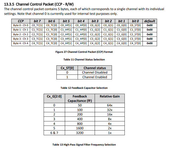
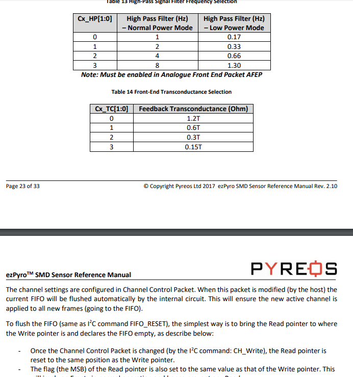
The 'Channel Control Packet' command will be containing 5 bytes in it and each byte is associated with a single channel. From the datasheet, byte-0 is associated with Channel-0 . similarly byte-1 to channel-1 and so on. Now, I can configure 'Channel Status', Feedback Capacitor' 'HP Signal Filter Frequency' and 'Front End Trans-conductance' of each channel by changing the bit sequences.
I did something like this:bit:7 -- bit:6 -- bit:5 -- bit:4 -- bit:3 -- bit:2 -- bit:1 -- bit:0
0 0 1 1 0 0 0 1But I couldn't figure it out what setting would be appropriate and would this setting be same for all four channels (Ch4:Ch1, except Ch0 as the datasheet says: "Note that channel 0 is currently used for internal test purposes only.") ?
And how to send this configuration to the sensor?
chnl_ctr = i2c.writeto_mem(0x65, 0x10, 5)Here, '0x65' is the I2C address, '0x10' is the 'COM Code' (the address of the channel?) provided in the datasheet for 'Ch-write' and 5 is the number of bytes passed to that address. So, how can I send the configuration to channel via this instruction?
I am confused about the Analogue settings as well.
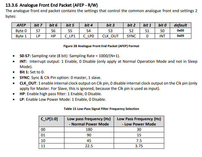
From the datasheet what I understood is, the 'Byte 0' will be '0x00' if we are following the
Sampling Rate = 1000/(N+1).And the 'Byte 1' can be:
bit:7 -- bit:6 -- bit:5 -- bit:4 -- bit:3 -- bit:2 -- bit:1 -- bit:0
0 1 0 0 0 1 0 0Here, do I need to use 'High Pass' filter? Should I disable 'CLK_OUT' (internal clock output)? Would 'SYNC' be '1' as our I2C is slave? 'Bit 1' is by default set as 0. Shall I enable the 'interrupt'?
The 'FIFO' read output (both for Active and Full channel) are changing every time I run the code for the same settings like below:
I2C Address [101]
Channel Control: 1
Analog Settings: 1
Analog Read: b'\x05\t\t\t'
FIFO_Read_Active_Chnl: b'\x00\xd8\x11&m&m&&&&&&&&&&'
FIFO_Read_All_Chnl: b'\x00\xd8\x11\x00\x00\x00\x00\x00\x00\x00\x00\x00\x00\x00\x00&m'
I2C Address [101] Channel Control: 1 Analog Settings: 1 Analog Read: b'\x05\t\t\t' FIFO_Read_Active_Chnl: b'\x00\xdc\x88msmsmmmmmmmmmm' FIFO_Read_All_Chnl: b'\x00\xdc\x88\x00\x00\x00\x00\x00\x00\x00\x00\x00\x00\x00\x00ms'I2C Address [101] Channel Control: 1 Analog Settings: 1 Analog Read: b'\x05\t\t\t' FIFO_Read_Active_Chnl: b'\x00\xbf\xc7\x7f\x1b\x7f\x1b\x7f\x7f\x7f\x7f\x7f\x7f\x7f\x7f\x7f\x7f' FIFO_Read_All_Chnl: b'\x00\xbf\xc7\x00\x00\x00\x00\x00\x00\x00\x00\x00\x00\x00\x00\x7f\x1b'I ran it consecutively within a minute.
I know I have asked too many basic questions and just hope that it doesn't annoy you but I badly need these basic understandings, otherwise I'm feeling really frustrated. Please help me to learn the mistakes I'm making in understanding the datasheet and programming.
Looking forward to your kind guidelines.
Regards
-
So, here I'm getting the Current output as '0' means nothing is there although as a 'Methane' sensor, it should show some values as methane is present in the open air.
No you dont read 'methane value', 0x12 command, ANA_READ return analog settings 'datasheet 13.3.6' (not analog value). In this case you read b'0x00\t', that mean 0x00,0x09 and it's default analog setting so your i2c communication seem correct.
Once your device is posered up, it will start in low power mode. You have to wake up it(Wake up command), then send Channel configuration (13.3.5) and Analog setting (13.3.6) , after that wait some time and read from fifo the expected value.
P.S. I haven't used any pull-up resistor in the I2C bus.
Not a good think, how have you set the CS signal of your sensor ? If not connected to +3.3V your sensor cannot be waked up.
Regards
-
@Eric73 Thanks for the suggestion.
I tried something like this:
from machine import I2C

i2c = I2C(0, I2C.MASTER)
i2c = I2C(0, pins=('P10','P9'))
print("I2C Address", i2c.scan())

value = i2c.readfrom_mem(0x65, 0x12, 2)

print("Current:", value)
After running it, I'm getting output as:
I2C Address [101]
Current: b'\x00\t'
So, here I'm getting the Current output as '0' means nothing is there although as a 'Methane' sensor, it should show some values as methane is present in the open air.
I tried to go through the datasheet but couldn't figure out anything. Would you please have a look into the datasheet and my code and guide me?
P.S. I haven't used any pull-up resistor in the I2C bus.
Regards
-
Could you please stretch a bit about how to set up the sensor correctly?
Well at least you have to set sampling clock, irq setting, digital filter and so on as a lot of other sensor. Datasheet show 18 command you can send to it, so at least you need send some command to perform your need.
Do I need to add external pull-up resistors at the sensor end?
As good practice, alway have some 4.7K pull-up resistor on I2C bus. You just have to check your low power requierment if you want to do very low power consumption when putting esp32 in deep sleep.
-
@Eric73 Thanks a lot for your reply.
WARNING : Be sure that your sensor doesn't need I2C clock stretching because as far i know, it's not supported by firmware (https://forum.pycom.io/topic/331/i2c-clock-stretching )
I couldn't find any mention about 'Clock Stretching' in the sensor datasheet. I have attached the datasheet here (Sensor_Datasheet-min (3).pdf). Although the images are blur as I had to compress it extremely to upload here.
But you still have to read and understand your datasheet sensor to set it up correctly to have your correct value.
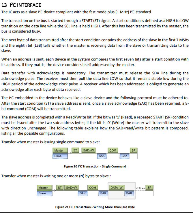
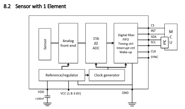
Could you please stretch a bit about how to set up the sensor correctly? Did you mean the physical connections from sensor to pycom? The I2C connectivity described in the datasheet is as below:
(and don't forget the pull-up on both line SCL,SDA)
Doesn't Pycom has internarl pull-up resistors? Do I need to add external pull-up resistors at the sensor end?
Sorry too many novice questions but your answers will help me to learn and understand.
Regards
-
@Oridroo said in How to read out the output of 'ezPyro SMD I2C Pyroelectric Infrared Sensor' via I2C command?:
Is it that simple or I'm just totally wrong?
Yes it is simple and correct.[That's why i like python for none business job]
R/W, ACK,NACK,START,STOP and other I2C stuff is not at your charge (low level driver do it for you). WARNING : Be sure that your sensor doesn't need I2C clock stretching because as far i know, it's not supported by firmware (https://forum.pycom.io/topic/331/i2c-clock-stretching )But you still have to read and understand your datasheet sensor to set it up correctly to have your correct value.
Before starting your application code, i suggest you to start by a code with i2c.scan() to check if you have correctly set i2c wire (and don't forget the pull-up on both line SCL,SDA)