RMT preipheral won't transmit?
-
Hi all,
I have been trying to use the RMT peripheral to transmit a pulse stream but I can't get it to work. Not sure if I've missed something.
I have a Wipy and an Expansion board V3.1. All firmware is up to date. I'm using VS code with Pymakr plugin to program the board, running under Manjaro Linux. I am using Xoscope to view the output pulse train.
I have another ESP32 based board (a Heltec WiFi kit 32) and I can program the RMT peripheral on that board using C (with VS code and PlatformIO plugin and the esp-idf functions (rmt_write_items etc) ) and it works perfectly. But I can't get it to work on my Pycom board.
Here is my test program# This is your main script. print("Hello, world!") import pycom pycom.heartbeat(False) from machine import RMT from machine import Pin chanPulse = [1000, 2000, 1000, 2000, 1000, 2000, 1000, 2000, 11000] duration=() ppmOut = Pin("P18", mode=Pin.OUT) ppm = RMT(channel=4, gpio=ppmOut, tx_idle_level=RMT.LOW) while(True): del duration duration = () for i in range(8): duration = duration + (chanPulse[i], 300) syncPulse = 22500 - sum(duration) duration = duration + (syncPulse, 300) ppm.pulses_send(duration, start_level=RMT.HIGH) #, wait_tx_done=True) # print(duration)Pretty basic. Have I left something out, or is there something else I need to do to get it to work?
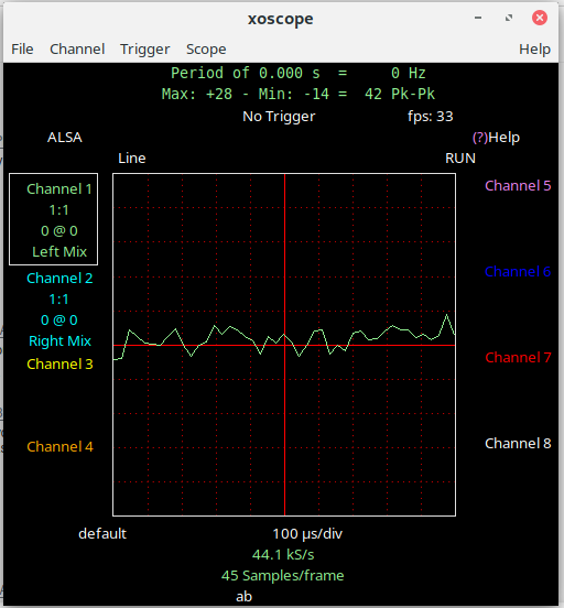
FWIW this is what I see on xoscope. Just noise.
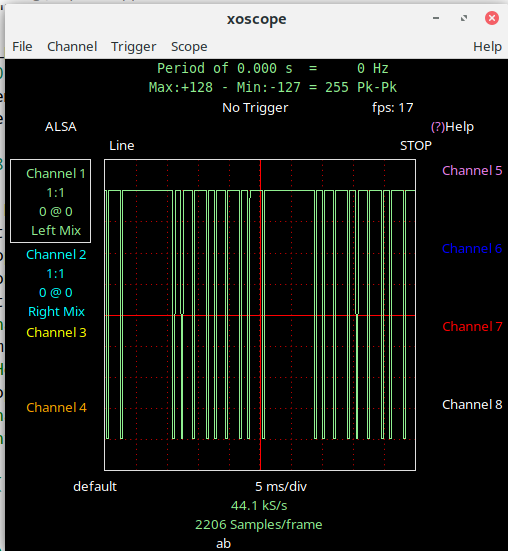
And this is what it should look like.
All advice gratefully received.
-
@mogplus8 P5 and P7 are fine. The ADC's are limited to 8, P13 - P20, since only ADC1 can be used. P4, P8 and P23 are connected to the SD Card adapter on the expansion board. If you want to use the SD card, you cannot use the for other purposes. Otherwise you can use them. The USB is connected through a USB/UART bridge on the expansion board to UART0 on P0 and P1.
-
@robert-hh good grief. I picked P12 as it was the easiest one to find on the board being in the corner, and my eyesight ain't what it used to be. How about P5? That doesn't seem to have much attached to it, that I'm interested in at the moment anyway... or P7 maybe? Future plans involve lots of ADCs (10 of), a SPI connection and using the usb connector.
;-)
-
@mogplus8 Be careful with P12. You can use it with a WiPy2, but on all newer boards with PSRAM P12 is used for switching the WiFi antenna. So using it will interfere with WiFi.
-
Hi @robert-hh and apologies for taking so long to get back to you. Every time I looked in this forum over the last few days I couldn't find my post, so I figured it must have been sitting in somebody's inbox waiting for approval or something. Obviously it wasn't as you found it almost immediately. I've only just managed to find it now!
So thanks for the tip, I'll try a different pin.
(ten minutes later)
Well that did it! I changed to pin 12 and it now works perfectly!
edit well, not perfectly. There is another problem but I'll start a new thread for it.
thanks again
;-)
Whooops, got t his in the wrong place somehow..., it's a reply to @robert-hh 's post.
-
@mogplus8 P18 is an input-only pin. You cannot set it to output mode. That applies to P13-P18. See the pin-out sheets.
Edit: I agree that the firmware should raise an exception on the attempt to set output mode on P18.