Current sensor 15A SCT-013
-
@robert-hh Thanks for your suggestion! I understand what you trying to say until this part "If the time for reading a value is larger, you'll have somewhat less noise. This time should be a integer multiple of the wave period. For 50 Hz, a multiple of 20 is fine, for 60 Hz a multiple of 50. So taking a multiple of 100 is good for both frequencies."
do you mean that at the coding the time I should modify it
time1 = time x 100 and all time change it to time1?
sorry.
-
@vicky_ The transfer ratio is hard to guess, because there are some unknown figures in between, like the transfer function of your sensor. That is 1Veff at 15A. So at 5 A it should deliver 0.333Veff. But i did never determine the remainder of the transfer function.
What you should do is to take the current of the hairdryer with an known good Multimeter and determine a factor from that. The ESP32 ADC is non-linear, especially at 11 dB attenuation. But the mid range values should be OK. Using 6 dB attenuation the linearity is better. But then you'll need a different interface circuit.
Yes, at low currents the ADC noise and the phase noise of the sampling steps in. If the time for reading a value is larger, you'll have somewhat less noise. This time should be a integer multiple of the wave period. For 50 Hz, a multiple of 20 is fine, for 60 Hz a multiple of 50. So taking a multiple of 100 is good for both frequencies.
-
@robert-hh Hello. The coding you shared, it works! Thanks a lot.
I use it to measure a hairdryer rated 1000w to 1200w.
when hairdryer is off I get 0.something.
when I open level 1 I get 10. something.
when I open level 2 I get 45. something.
when I open level 3 I get 71. something.
I chose the maximum value 71.something and divide 512 (9 bits ADC) times with 3.3v and 15A.eg:
((71.22/512)*3.3)*15 = 6.86Abut the maximum current should be 1200/240v =5A, right?
or my calculation is wrong?
I used it to measure a phone charger but it has no different with when it is off, maybe the current is too small.
once again, thanks

-
@robert-hh Thanks for your clear explanation! I will try it and see how.
Yea, I only feed one single wire which is the live wire. Thanks for your remind. Thank you
-
@vicky_ I used adc=9 bits, because thats the useful resolution for the ESP32 ADC. You may also go for 12 bits, but all you will get is more noise, not more precision.
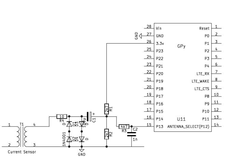
Yes, you can use also your circuit, as long as you connect it to 3.3V and not to 5V. The two circuits are effectively the same. The reason I prefer mine is, that one side of the sensor output is connected to GND. But that is more a flavour than technical need. I strongly reccomend the protection circuit. The sensor is a low impedance source, and saturates at +/- 10V, which, when applied to the ESP32, will most likely kill your LoPy.
Bot the sensor and the software work with AC only. The sensor if an AC transformer. With DC the output is 0. The software returns the amplitude of a fixed frequency in the input signal. Since the sensor is used for mains current, typical frequencies are 50 or 60 Hz.
maybe a note for using the sensor: You must feed only a single wire though the sensor. Loads are connected typicall with at least two wires. Only one of them must be passed through the sensor. Otherwise, the output signal of the sensor is 0.
-
@robert-hh Hello, thanks for your reply! sorry for late reply because I was trying to digest your information. I have read up a bit about "goertzel-Algorithm" but Im not very understand the coding and the diagram. Why adc bits=9? Can I get the DC voltage using that coding? by diving the value obtained 512 and times with 3.3. like this (x/512)x3.3
I also confused with the connection of the current sensor. can I use back my own connection because this can work with Arduino.
https://learn.openenergymonitor.org/electricity-monitoring/ct-sensors/interface-with-arduino?redirected=true
just that i dont have the Emon Lib.Sorry if I ask silly questions! I really appreciate your help!
-
@vicky_ I shoud add that I used another way of connecting the sensor, which also limits the input voltage, which can go up to +/-10 V in over current conditions:
Input voltage w/o limitation:_
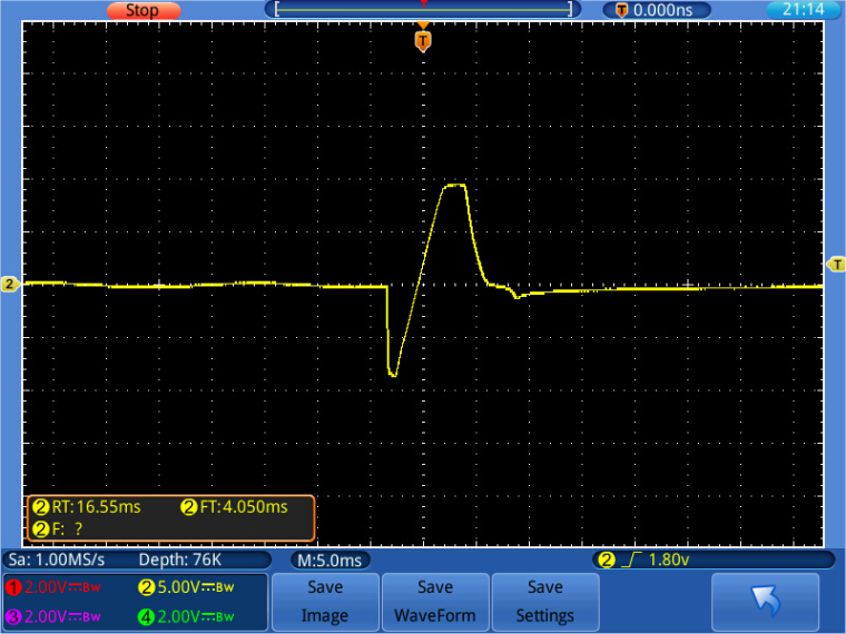
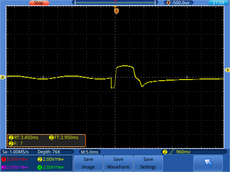
Input voltage with limitation:
-
@vicky_ For use with the LoPy, you have to attach it to use the 3.3v Pin instead of the 5V pin. The output of the sensor is a sine wave with the frequency of the AC current you're measuring. This sensor is made for AC only, and typically at low frequencies, like 50 or 60 Hz.
The ADC input of the ESP32 is noisy. So you have to average over a few measurements for DC measurements. For AC it is more difficult. If you just want to take the current of the mains signal at a fixed frequency, you can do something like a fixed frequency amplitude analysis. Look out for the "goertzel-Algorithm", which does that w/o needing to sample a buffer full of data. A sample implementation is below:# import gc import math import array from utime import sleep_ms, sleep_us from machine import ADC, Timer, idle, enable_irq, disable_irq, Pin # # acquire ADC values. The paramters of the constructor are: # 1. the mains frequency (number, typically 50 or 60) # 2. the sampling period (ms). The default is 2 ms. # class Acquire: def __init__(self, freq=50, *, sample_period=2): self.sample_period = sample_period self.omega = 2.0 * math.pi * freq / (1000 / sample_period) self.coeff = 2.0 * math.cos(self.omega) self.adc = ADC(bits=9) def start(self, pin, time=200): gc.collect() # avoids automatic gc during sampling self.pin_adc = self.adc.channel(pin=pin, attn=ADC.ATTN_11DB) self.samples = time // self.sample_period self.count = 0 self.busy = True self.q1 = 0.0 self.q2 = 0.0 self.alarm = Timer.Alarm(self.read_adc, 0, ms=self.sample_period, periodic=True) def stop(self): self.alarm.cancel() def read_adc(self, alarm): self.q0 = self.pin_adc() + self.coeff * self.q1 - self.q2 self.q2 = self.q1 self.q1 = self.q0 self.count += 1 if self.count >= self.samples: self.alarm.cancel() self.busy = False def result(self): while self.busy == True: sleep_ms(self.sample_period) amplitude = 2 * math.sqrt(self.q1 * self.q1 + self.q2 * self.q2 - self.q1 * self.q2 * self.coeff) / self.count # if phase is required: # real = self.q1 - self.q2 * math.cos(self.omega) # imag = self.q2 * math.sin(self.omega) # amplitude = 2 * math.sqrt(real * real + imag * imag) / self.count # phase = math.atan2(real, imag) # return amplitude def reading(self, pin, time): self.start(pin, time) return self.result() # while True: acq = Acquire(50) # 50 Hz value = acq.reading("P13", 1000) print (value)