• ADC conversion values

    Discussion adc adc accuracy lopy4 sensor
    4
    0 Votes
    4 Posts
    279 Views
    robert-hhR
    @mrks-tsk The capacitor has to be placed between ADC input and GND. In your diagram at the VBATT side.
  • How to distinguish sensors?

    WiPy 2&3 lopy wipy sensor
    6
    0 Votes
    6 Posts
    438 Views
    W
    @robert-hh Thank You!
  • SPI + MS5540C driver

    Discussion spi sensor ms5540c
    2
    0 Votes
    2 Posts
    348 Views
    T
    hello there, Did you manage to solve this issue? :) Thanks
  • 0 Votes
    4 Posts
    382 Views
    FridaF
    Gern geschehen. Grüße aus Dänemark
  • Help me please Sensor SHT20 SHT21

    LoPy lopy wipy sensor
    2
    0 Votes
    2 Posts
    254 Views
    W
    Doesn't anybody have such a sensor running and could help me get mine to run?
  • 0 Votes
    5 Posts
    483 Views
    W
    @robert-hh Okay, thanks for your help.
  • LOPY SPI Mikroe click module

    LoPy lopy spi sensor
    4
    0 Votes
    4 Posts
    497 Views
    robert-hhR
    @johncaipa said in LOPY SPI Mikroe click module: adc = (((buf[0] << 8) | buf[1]) & 0xfff) >>1 That one is wrong. You have to shift the raw value befor masking. The lowest bit of the returned value will not be at bit0 of adc, so you have to shift to to the right. Reason: The adc starts shifting out values at the 2nd (or third?) clock cycle, and SPI will create 16 clock cycles. So there are like 14 bits in the result buffer, of which only the high order 12 bits are valid. The others have to be discarded and the value has to be properly aligned. If you use a separate CS pin, you can simply use spi.read_into(). spi.read_into(buf) adc = ((buf[0] << 8) | buf[1]) >> x) & 0xfff x should be a value between 1 and 3. Best is to determine it experimentally. The conv variable and write_readinto() is only used to create the CS signal at the MOSI pin. By using an appropriate pattern for conv, like 0x8000, 0xc000, of 0xe000, you can shift the CS signal in clock steps, making the final shift of the result obsolete. So doing that save a pin and saves a few instructions.

  • DS18b20 temperature values format

    SiPy ds18b20 format sensor
    3
    0 Votes
    3 Posts
    623 Views
    robert-hhR
    @brossingo I'm using this lib for Pycom devices: https://github.com/pycom/pycom-libraries/tree/master/examples/DS18X20 It works well. I tested it only with a single device on the bus, but there is also support for multiple devices.
  • Onewire library function does not work

    Pymakr onewire ds18b20 sensor
    2
    0 Votes
    2 Posts
    543 Views
    robert-hhR
    @brossingo G5 is an input only pin, like G4, G0, G3, G31 and G30. Try another pin, like G22 or G17 or G7 or G6 or ....
  • 0 Votes
    2 Posts
    549 Views
    danD
    Hi @nobo23 Are you trying to connect multiple sensors to the WiPy and communicate with them via Bluetooth? Connecting multiple BLE nodes to the WiPy is possible. You can find our BLE examples here. Hope this helps, let me know if you have any questions!
  • 0 Votes
    4 Posts
    736 Views
    C
    Hello. Recently I've been reading blog - pro4people.com and I have to admin that AWS cloud services got my attention. What ERP system would you recommend if we want to use amazon website services? Is it possible to use SAP on this network? Let me know please, since we are completely new to this subject.
  • 0 Votes
    3 Posts
    970 Views
    pierrot10P
    @robert-hh Oh! thank, I missed it. Great I am happy to try it, this evening! Thank a lot!
  • Current sensor 15A SCT-013

    LoPy sensor current lopy
    28
    0 Votes
    28 Posts
    4k Views
    robert-hhR
    @StefanoF I made a few more tests with the most recent code I have posted (which is the initial goertzel code). a) test for phase jitter. Instead of reading the ADC, i just supplied a artificial 50Hz sine with an amplitude of 50 and an offset of range/2 into the algorithm. Result: constant 49.99993, which means that there is no phase jitter. b) I connected the interface network, but not the sensor. Result: Output values between 0.005 and 0.03. Since the output value of 1Veff is about 240, that is equivalent of ~60µVeff, or about 1 mA through the sensor. c) connect a battery with 1.5V to the input. Result: values of about 0.5 -> Noisy battery! d) connect the SCT013 with no current. Value of 0.04 +/- 0.03. That's about 160µVeff of 3 mA (or 0.5 W at 230V) through the sensor. So it looks as if the sensor picks up some noise, but still ok. e) Using an external ADC (mcp3201). Result: values of 0.05. Slightly worse than using the internal ADC. Lesson learned: I will stick with the initial solution. The challenge is to proper shield the interface network and the cable from picking up unwanted noise.
  • 0 Votes
    6 Posts
    1k Views
    joearkayJ
    @robert-hh - Further to this - I actually haven't got the sensor to hand (awaiting shipment), but once it arrives, I'll measure the current draw at 3V3 to confirm that the datasheet is accurate.
  • SPI Baudrate Limited to 10000

    WiPy 2&3 spi sensor
    1
    0 Votes
    1 Posts
    651 Views
    No one has replied
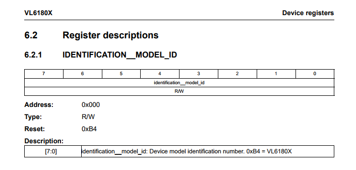
  • VL6180X on LoPy I2C sensor driver

    LoPy lopy i2c sensor
    13
    1
    0 Votes
    13 Posts
    4k Views
    K
    @chumelnicu Hey, you can look it up here (scroll down) or try to transcribe the Adafruit library
  • 1 Votes
    15 Posts
    4k Views
    R
    @robert-hh Thanks for your reply. I only have two sensors at hand now. No matter which one I use, it's ok. Since the principle is completely different. For the two sensors, do you familiar with them? Can you teach me some direction about how to program if you know. It's hard to find the same topic in the website and I am extremely confused now. Thanks! This is the image of the sensor, which provided by my supervisor.[image: 1519505208052-hc-sr04-sonar-sensor.jpg] [image: 1519505214245-ultrasonic_6.png]
  • Reading analog voltage with ADC and attenuation

    LoPy adc sensor attenuation
    9
    0 Votes
    9 Posts
    4k Views
    H
    the scale factor is Vcc / 5120 per 1 mm