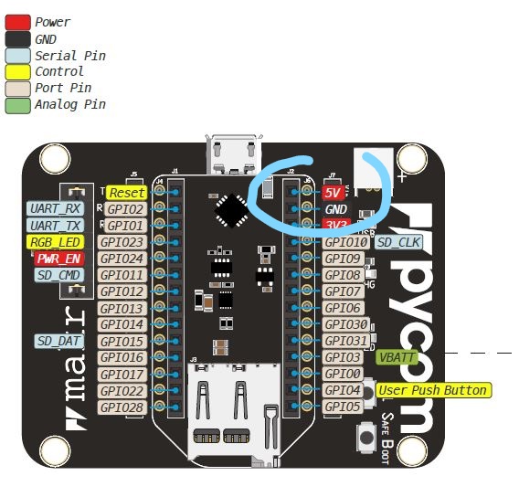
@matthew said in Relay and solenoid valve:
e if i can power the relay using the 5v o
The "5V" label of the expansion board v. 3 is in reality the voltage input value.
It can be around 5V when the board is connected with USB cable (if attached to a 5V source), but it is not when is power is sourced by the LiPo battery.
On board there is a TPS2115A, that switches from one source to the other when, for example the battery is connected and we plug the USB cable.
The Vin can be from 3.5 to 5.5 V.
Solenoid valve control
You can use many different options to control the solenoid valves as well as ways to power the solenoid valves and mechanical relay or equivalent driver.
I personally prefer isolated solutions like optocouplers, solid state relays (photo MOSFET) (price went down in last years), ...
An alternative can be, if You need to drive more than one, darlington transistor arrays like ULN2003, the low voltage ULN2003LV, or the newer equivalent TPL7407L.
You can easily found mechanical relay boards with onboard optocoupler. You need to heck the datasheet to look for the mA at 3.3V that they sink.