I2C accelerometer model MMA7455
-
Hi all!
This time i'm trying to make work the accelerometer MMA7455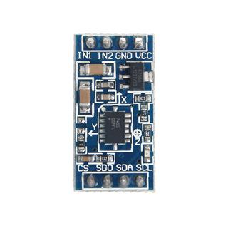
The MMA7455 schematics are this:
http://www.geeetech.com/Documents/MMA7455_Schematic Download PDF .pdfAnd the specs of the sensor (ADXL345) that carries the MMA7455 is this:
https://www.sparkfun.com/datasheets/Sensors/Accelerometer/ADXL345.pdfI've been trying to do every kind of things to make this little chip work, but no success at all. Almost always getting OSError: I2C bus error
I'd like to start with a very basic test i'm doing, reading from the DEVID registry of the ADXL345 sensor.
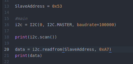
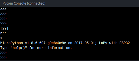
What i get after doing that is:
Based on the sensor documentation i think that my previous code is fine:
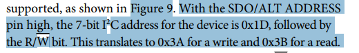
An alternate I2C address of 0x53 (followed by the R/W bit) can
be chosen by grounding the SDO/ALT ADDRESS pin (Pin 12).
This translates to 0xA6 for a write and 0xA7 for a readIf someone understands what's happening please share that precious knowledge.
I still dont understand what [59, 60, 61] means by the way...
-
@jmarcelino @livius @robert-hh
Hey all, thx a lot for helping me this last days with this driver. This is the code i have until now... it's a shame that i didn't make it, but i think that i could have broken the sensor when i plugged CS to 5v instead of 3V3.
I think i will buy another one, that will take some weeks until it gets to Uruguay :PAnyway, this is the code we've made until now, maybe it's useful for someone else. It's not throwing the ugly i2c bus error anymore, but the device id registry is returning always zero, and that's bad... not sure if the device is broken or what, but comparing this code with the implementation @livius has referenced, and with other implementations i found on google for other languages, it looks like the retrieval of the device id is the first action almost everyone does, so... i dont know.
from machine import I2C
from machine import Pin
from machine import Timer
import timedef DelayUs(us):
Timer.sleep_us(us)#i2c slave address
SLAVE_ADDRESS = 0x1D#registers
REG_POWER_CTL = 0x2D
REG_BW_RATE = 0x2C#connected to SDO and CS of MMA7455
CS = Pin("P23", mode=Pin.OUT)
CS.value(1)
CS.hold()DelayUs(1000)
#main
i2c = I2C(0, I2C.MASTER, baudrate=100000)
print(i2c.scan())def setPowerCtrl(measure, wake_up=0, sleep=0, auto_sleep=0, link=0):
power_ctl = wake_up & 0x03
if sleep:
power_ctl |= 0x04
if measure:
power_ctl |= 0x08
if auto_sleep:
power_ctl |= 0x10
if link:
power_ctl |= 0x20
i2c.writeto_mem(SLAVE_ADDRESS, REG_POWER_CTL, bytes([power_ctl]))#*****************************
#******* main logic **********
#*****************************
data = i2c.readfrom_mem(SLAVE_ADDRESS, 0x00, 1)
print("DEVID: " + str(bin(data[0])))#set power characteristics
setPowerCtrl(1, wake_up=0, sleep=0, auto_sleep=0, link=0)
-
@livius said in I2C accelerometer model MMA7455:
"{0:b}".format(5)
Uhhh good, looks much better than my awful function :D jajaja, sorry for breaking your eyes but didnt know that
-
@pablocaviglia
for bin formatthing use:>>> bin(5) '0b101' >>> "{0:b}".format(5) '101' >>>to see more in memory
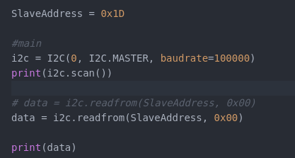
data = i2c.readfrom_mem(SlaveAddress, 0x00, 5) #increase value to 5 bytes from memoryand look what you get
-
@livius said in I2C accelerometer model MMA7455:
data = i2c.readfrom_mem(SlaveAddress, 0x00, 1)
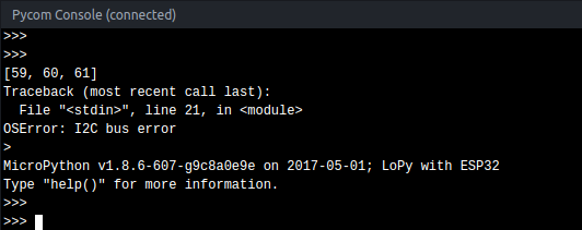
Well... at least something changed!
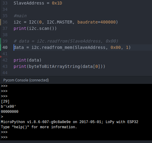
The 0000000 at the end is the way i found to show the byte in binary string. Btw is this way correct to do that ?
def byteToBitArrayString(rcv):
bitArrayStr = "1" if rcv&0 != 0 else "0"
bitArrayStr += "1" if rcv&1 != 0 else "0"
bitArrayStr += "1" if rcv&2 != 0 else "0"
bitArrayStr += "1" if rcv&3 != 0 else "0"
bitArrayStr += "1" if rcv&4 != 0 else "0"
bitArrayStr += "1" if rcv&5 != 0 else "0"
bitArrayStr += "1" if rcv&6 != 0 else "0"
bitArrayStr += "1" if rcv&7 != 0 else "0"
return bitArrayStr
-
@pablocaviglia
try this insteaddata = i2c.readfrom_mem(SlaveAddress, 0x00, 1)
-
@livius
I've checked that code, really nice!
I'm not receiving the i2c bus error anymore, but based on docs, when querying the the DEVID registry i should get this: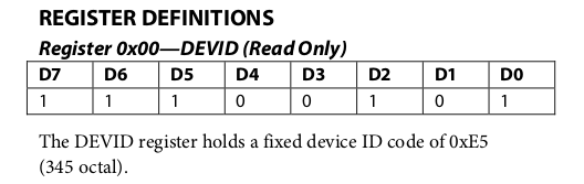
My code does this:
And i got this:
PD: By the way, how do i earn reputation points in this forum? I can only send 1 message each 10 minutes... boring!
-
@robert-hh :+1:
-
@pablocaviglia
to not starting from scratch try adapt this
https://github.com/alexismeneses/py-adxl345/blob/master/lib/adxl345/base.py
-
@pablocaviglia No. It's just the way it has to be coded at the physical interface, not the API you are using. Setting the R/W bit is done by the underlying functions. All you have to do is use the address 29 in the call of python methods.
-
@robert-hh So you say that the slave address would change from read to write.
If i want to read/write it would be:i2c.readfrom_mem(0x3B, 0x0, 1)
i2c.writeto_mem(0x3A, 0x0, value)Is that what you mean?
-
@pablocaviglia The I2C address is located in bits 1..7. Bit 0 is the R/W bit.
0x3a (58) is 0x1d (29) * 2, and 0x3b simply adds 1 in bit 0.
-
@jmarcelino
Very good point man! I've pulled up P23 on pycom to get 3.3v, then i plugged CS and SDO in there, and things got changed a lot.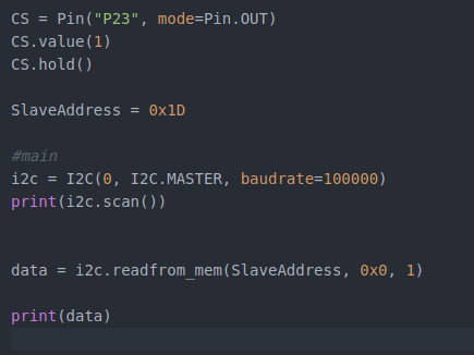
And i got this when running:
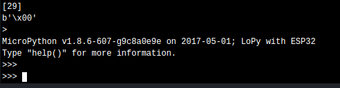
Much much better, no I2C Bus Error anymore.
Just to be sure i tried to pull down the pin P23 to verify if it stops working, and it does stop effectively.
Also another very good thing is that based on documentation, the slave port to start using is '1D', and now i'm effectively getting 29 (1D) while scaning ports, instead of 59,60,61.<><><><><><><><><><><><><><><><><><><><><><><><><><><><><><>
 <><><><><><><><><><><><><><><><><><><><><><><><><><><><><><>
There's something that i dont understand from that document section. It says that the 0x1D followed by the R/W bit translates to 0X3A for write and 0x3B for read.... what does that mean?
-
@livius
Yes, just using the default initialization, P9 - SDA, P10-SCL
-
If you look at the the schematic the CS pin on the board shouldn't be connected to 5V. It's comes from 3.3V.
The chip pin is not made for that and also you're connecting the 5V supply to a regulated 3.3V via the 4.7K pull up...
-
@robert-hh said in I2C accelerometer model MMA7455:
RT9161
Ah - i see now i ommit this on the first link with schematic
Then two things @pablocaviglia
Where do you conect your SDA, SCL. Which pins on Lopy?
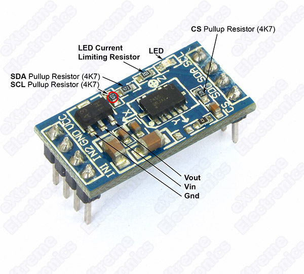
You use default initialization of i2c then i suppose P9 - SDA, P10-SCL?I see on schematic that there is pull up resistor already on i2c
This is better picture of it
-
@livius said in I2C accelerometer model MMA7455:
Why 5V?
The module has an internal 3.3V regulator RT9161.
-
@pablocaviglia
Why 5V?
in documentation is
Supply voltage range: 2.0 V to 3.6 Vand all Pycom boards are 3V3. 5V can crash your Lopy.
And about other connections
Where do you conect your SDA, SCL. Which pins on Lopy?
You use default initialization then i suppose P9 - SDA, P10-SCL?
-
@jmarcelino yes, but i have sdo pulled down
-
Thx all for your interest. I've not get home yet, i'll do some tests based on what you said once there.
Anyway before leaving i took a picture of the current connections of the chip. Let me show you how does it looks now: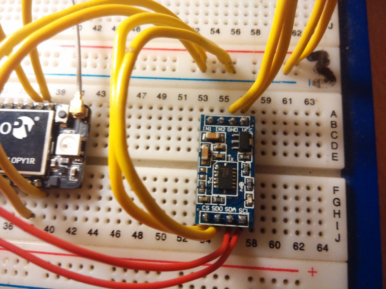
UP
GND -> GND
VCC -> 5VDOWN
CS -> 5v
SDO ->GND
SDA SCL -> both to idem on pycomHope it helps to deduce something!