[Pysense] How can I connect a sensor to the external IO Header
-
Hello all,
I am new with pycom and pysense. I could run the Pysense and take measure with integrate sensors. That's great.
Now, I wish to use my own moisture capcitive sensor and later to use a WatherMark sensor and I need analogic pin.
I wonder if the External IO pin of the Pysense can help?
For my future experience I would need 3 Analog input to read the measure and to Digial output to power the Watermark sensor.
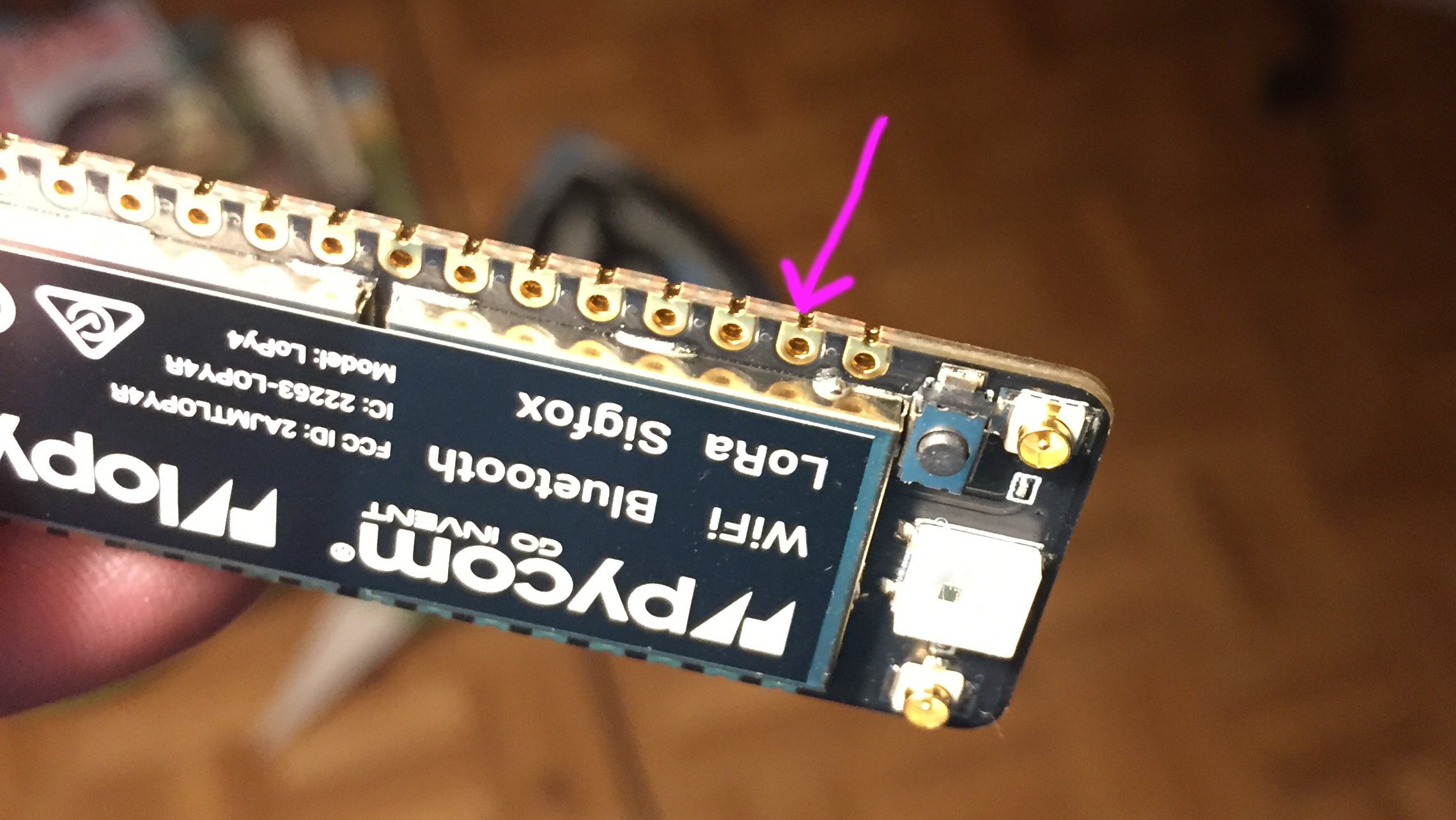
In that doc link text, it state that the IO1, IO4 & IO5 are connected to PIC.
What it is really a PIC?I wonder if those external IO can be use as analog input and/or analog input or which can be analog input
The best is to be able to make my future experience with the Pysense, otherwise, I will investigate to connect the Poly4 to an Raspberry Zero W (without Pysense) and investigate how to use 3 Watermark sensor, on tempearture sensor (soil temperature) and on capacitive moisture sensor.
Many thank for your help, tips and hints.
Cheers
-
Hi @pierrot10 The internal ADC has very poor performance. The non linearity is poor and it has a high noise floor. I think someone earlier suggested using an external ADC and I think that is very good advice.
-
@pierrot10
I see a problem with the schematics above, when reading multiple WM sensors the ground paths should be isolated:“
Sensors must be powered individually, and the ground must be isolated from sensor to sensor. Even if powered individually, an open ground path to another un-powered sensor can't be allowed. This is best accomplished using multiplexers to open and close the appropriate channels.
“
For additional details please refer to :
www.irrometer.com/200ss.html
-
@pierrot10
I’m afraid Seb has left Pycom but I’ll answer.Soldering a header to the side could work but not very mechanically stable. If it breaks it may take some of the pads.
I would recommend a female long pin stacking header for your application
-
@seb Dear Seb,
But would it possible or recommended to solder header on the side of the LoPy?
-
@jclo13 Hello,
I am on a good way, but I postponed that project due to other emergency tasks. I planned to be back with Pycom in a couple of weeks. I will update you.
-
@pierrot10,could you make it work? I am doing something similar but I am confused about which pins I have to use.
Thank you in advance
-
@seb Dear all,
Thank for your advise. I finally ordered an Extention boead that I just received. I will test my project. I think your previous statements are available for the extention board. Then just would like to have an advise to avoid burning my LoPy4 :o)
So I can resume as the following
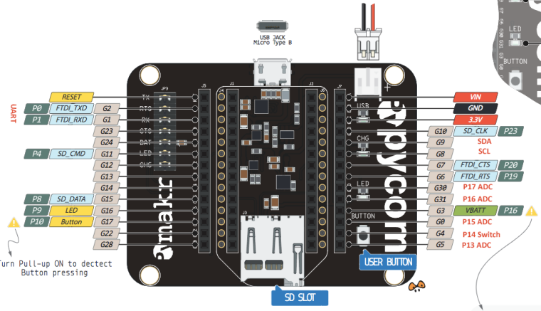
- P21 and P22 are reserved for SDA and SCL (I2C)
- P13, P15, P17, P18 can be used as ADC
But does P14 (Switch) and P16 (VBAT) P19 (RTS) and P20 (CTS) can be used as ADC as well, as they look like reserved for VBAT, RTS, CTS, etc...)?
I supposed I do not need a converted Analog to Digital? Can I directly connect my Analog input?
I will try this schema which is my favorite
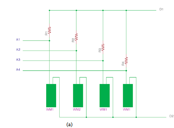
WMx are the moisture sensor.I first will try with one sensor. Then I will conect A1 to P13
D1 and D2 and two digital output, when D1 is HIGHT, D2 is LOW. D1 must be 3.3V. I will have to programm LyPo4 to altenate D1 and D2 to avoid corrostion and make an average of the result....Then I can use P6 and P7 for D1 and D2? P6 and P7 look like free and not use....
Then later, I will use 3 of the WM. Then I can connect A2 to P15 and A3 to P17
P18 can be reserved for a 4 sensors.IF all is correct, I will have another problem, because I would need (not sure) two more Analog measure. Then can P19 and P20 be used? What will be the impact on RTC and CTS?
Or, can I use P19 or P20 as digital inpout (waterproof temperature sensor)P16 confused me because , its states 'VBAT'. What does it meens? It's a VBAT output?
I am also a bit confused about P14
if you are not using this then you are ok to connect something else to itP14 could be the output the measure when the button is pressed?
Or, can I use as Digital Input for Rain gauge (magnetic switch)?Many, many thank for your clarification, it's help! (I hope, I was clear :o). )
Have a nice week-end!
-
On Pycom tboards there are two I2C hardware peripherals that can be used (+ 1 bit-banged software driver).
So You don't need to solder wires, just use the other I2C bus, the "1" one and use two of the GPIO pins that are available in connector of the PySense.
There are, as other wrote, ADC converters that has an I2C interface, for example, 4 (single ended) channels, there are ADS1015 (12 bit), ADS1115 (16 bit), 18 bit, 24 bit, ...
The advantage of this solution is that You can find ADC I2C chips with 1, 2 or 4 channels, that can be used single ended or for differential analog input, with programmable gain control, low drift internal voltage reference, ...As for the libraries there are a many examples or libraries in Python for several of I2C ADC, or can be derived, for example, from Arduino libraries.
For example for ADS1x15
[link text]https://github.com/robert-hh/ads1x15(link url)
-
time.sleep() is as a delay without saving battery energy?
That's correct, this is just for waiting a period of time not actually putting the CPU into sleep mode.If you are using a LoPy, SiPy or WiPy 2.0 you will require a deepsleep shield or pysense/pytrack in order to use deep sleep properly (The voltage regulator on these devices does not go into low power mode, and therefore uses lots of power in deep sleep mode, the extra boards fix this by removing power from the module). For all other pycom modules the deepsleep function works correctly and no external hardware is required.
One thing to note when performing deepsleep, upon waking up the device does not continue from where it left off, it restarts just as if you pressed the reset button.
As for what pins you should avoid using, it goes as follows:
- The sensors are connected via I2C on
SDA=P22andSCL=P21. You can connect more I2C devices to this. - The usb UART is connected to
P0andP1 - The onboard switch is connected to
P14(if you are not using this then you are ok to connect something else to it) - The SD-card is connected on
SD_CMD=P4,SD_CLK=P23andSD_DAT=P8(Same as above, if you don't use this, it's free to be connected to something else) P13is used for interrupts from the microcontroller on the pysense (avoid using)P3is connected to mosfets that disconnect power from the module (avoid using)
- The sensors are connected via I2C on
-
@pierrot10 said in [Pysense] How can I connect a sensor to the external IO Header:
@crumble said in [Pysense] How can I connect a sensor to the external IO Header:
You build a PCB which you place between the development and the expansion board (like the deepsleep board).
I meant the form factor of the board, not the deep sleep board itself. Sorry to wrote that not clear.
-
@pierrot10 Just to be clear, you don’t need the deep sleep shield with the LoPy 4, and you can achieve the same power consumption levels with
machine.deepsleep.
-
@pierrot10 said in [Pysense] How can I connect a sensor to the external IO Header:
time.sleep() is as a delay without saving battery energy? or is efficient as the deepsleep bpard.
it can't be so efficient as deepsleep. You have still cpu running, your program is still in memory and memory is power up. Deepsleep disable many hardware and you start fresh near like the reset press.
-
@crumble said in [Pysense] How can I connect a sensor to the external IO Header:
You build a PCB which you place between the development and the expansion board (like the deepsleep board).
This obeservation is not to bad but now I wonder which is the difference between
time.sleep(15)and the deepsleep board.
time.sleep() is as a delay without saving battery energy? or is efficient as the deepsleep bpard.
Can I use Pysense, Lopy4 and deppsleep board all together?
If time.sleep(9 is not saving energy, I should better make my own deepleep board as the schematic is oepn souce and adding connection to P13 to P20
@seb, may ask you two last thing :o). On the Pysense board, which are the pin I can not use. Which are the pin used by the sensors and other tasks that I can not use for my own additonal needs?
And can we order the pysens board without headers? In that way, I would be able to add my new board, below the pysense board.Thank a have a nice week-end
-
Maybe future pysense will have more rooms.
I see pyscan have few more haders i do not know details but i suppose it is
something what was proposed to expansion board changes?
https://forum.pycom.io/post/7562@seb can you bring light to this headers? And if possible future plans for expansion boards changes like pysense, pytrack and normal expansion board?
-
@pierrot10 said in [[Pysense] I can only solder wire on the bottom, which is not really clean.
This depends on your soldering skills ;) The external header is not a plug in as well.
IMHO you have two possiblilities for a cleaner look.
- Solder the wires to a connector and not directly to your sensor.
- You build a PCB which you place between the development and the expansion board (like the deepsleep board). On the PCB you can place plugs for all sensors. But this will add more height to your project.
Version 2 may look a little more professional and will be better for mass production, but 1 will be better, because you can use heavy duty connectors.
-
-
@seb Thank Seb for your reply. The other idea, would be to order an Poly4 without header. Then solder longer header (top and bottom) on Lopy4. Connect the Poly4 on Pysense and connect the sensores ont the top of the Poly4. In that way, I could use all pin of the Poly4 and the Pysens sensors.. Istn't? Thanks
-
Hi,
We have not open source the design of our modules or shields. The only products with available schematics are the deep sleep shield and the two oem reference boards.
With the way the pysense/pytrack boards are design the only way to access the adc pins (
P13,P14,P15,P16,P17,P18,P19andP20) is by soldering to the bottom of the female headers. If you used an expansion board you would be able to access these pins easier but like you would no longer have the sensors.You could solder the pysense and expansion board together using the external io pins (just connect power and the sensors are all on i2c which is exposed on
EXT_IO2andEXT_IO3) but that is also not a very neat solution.
-
@seb Dear Seb, thank again for your reply. It's a bit anooying because four of my additonnal sensor (Watermark and another capacitive mosture) need Analog input. I also plan to add a rain sensor (I am not informed about I2C or Analog)).
So, if I wanto to use the PYsense sensor additonal of my extra needs, I can only solder wire on the bottom, which is not really clean.I could use the expension board, but I will not have the benefict of the tested sensors of the Pysense
Is the Psysens schematic is opensource? I could modify it ad add extra pin to the Lopy4 Analog pin a create a PCB that I could share?
Or , the extention boars is the only way to have analog input? In that case I would have to create a separeted PCB with the Pysens sensors and connect it to the Extension board. Is there a open source shematic for the Pysense sensors only?
My project (idea) is to use Pysense board and to add
- 3 Watermark sensors,
- 1 rain gauge sensor
- one soil temperature sensor.
- One Oled LCD (I2C)
- May be, a RTC (I2C)
;o)
Cheers
Pierrot