DIY a Compact RC Switch
-
Good day~all,
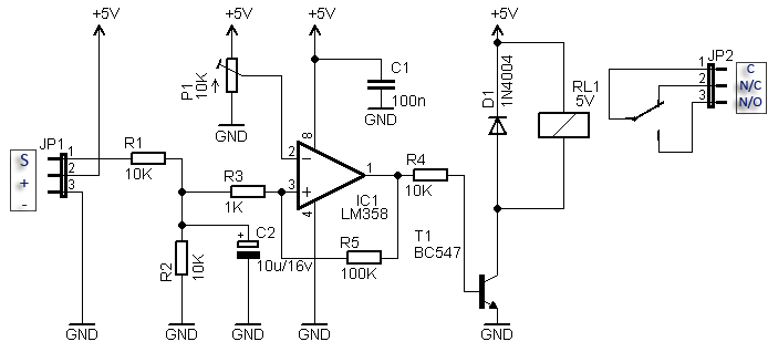
I have made a compact RC switch circuit,which built around the LM358 comparator reacts to a 50Hz PWM signal with a pulse width of around 1-2ms. If the reference voltage ( at pin2 of LM358 ) fixed by the 10K oitebtuineter is lower than the filtered signal voltage (at pin 3 of IC1), the comparator output goes high, relay driver BC547 (T1) is switched on and the 5V relay (RL1) works. The 100K reistor ( R5) provides small hysteresis to prevent the comparator from responding to every minor wavering in the voltage on the non-inverting input (pin 2) of the comparator. The aim I bluit this circuit is to control the on/off of lighting on radio control projects.
Well,Comparing with the above circuit,the only differences are that1).The relay driver(T1) I used is BC547A instead of BC547. This is the BC547A PDF.
2).My circuit has a 20K pot and it will not work,I am having a hard time figuring out the pin 2 input,giving a negative voltage.
Can anyone here help me?
Best regards~
-
@Len-Wang Since there is no negative supply, the voltage at pin 2 should always be positive. The difference between 10k and 20k for the pot is negligible. I would make R4 smaller, like 1 k. I do not know how much current the relay needs, but that should match the current gain of the BC547A (110-220) and R4.
What is the voltage at Pin 1, the op-amp output. Does it ever change?