SDI-12 Soil Moisture Probe Help
-
Hi,
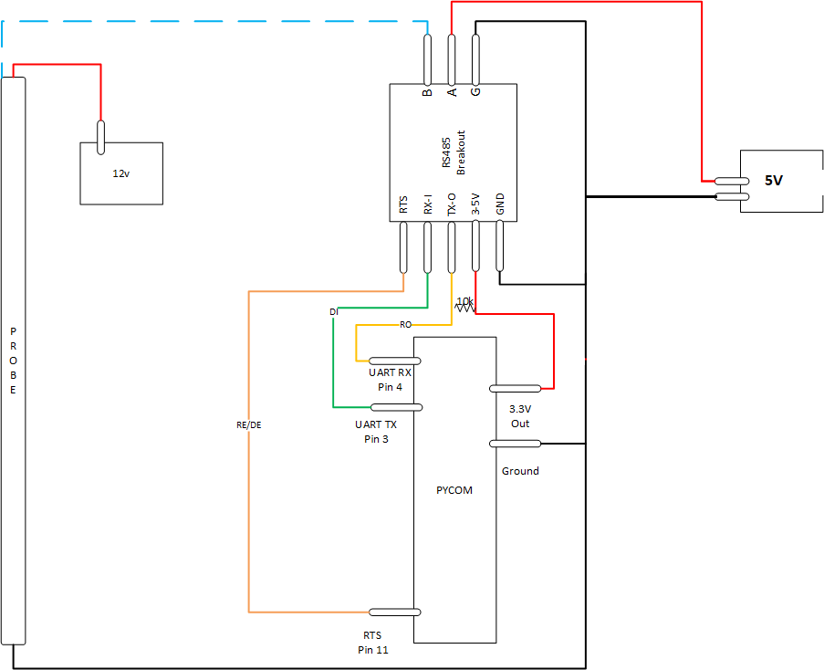
I have a large soil moisture probe which uses SDI-12 protocol :( I have connected my LoPy to an expansion board then into a RS-485 Breakout board like below.
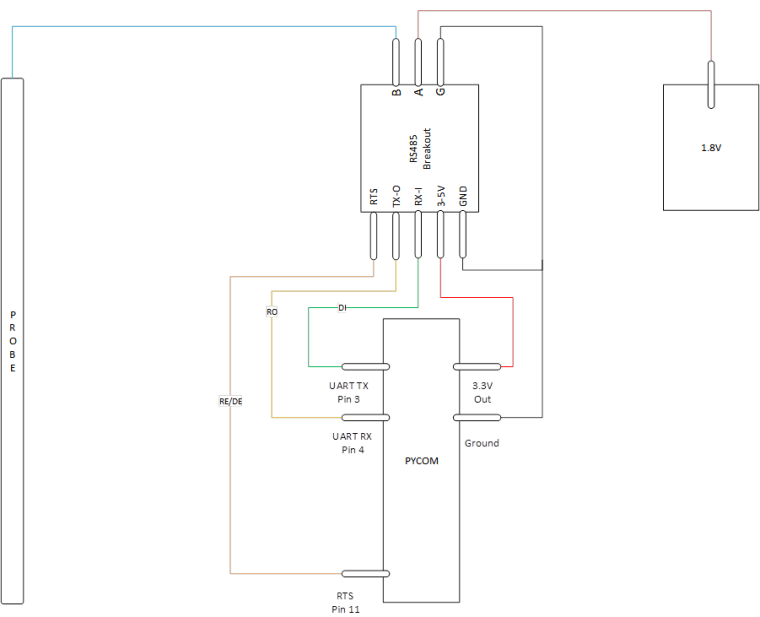
Here is my code just to test the output of a SDI-12 request
import network
import time
import pycom
import machine
import gc
import socket
import utime
from machine import RTC
from machine import ADC
from machine import Pin
from machine import UART
from network import LoRa

execfile('/flash/Network/LoRa.py')

f_device = open('/flash/Config/Device_Details.txt', 'r')

device_setting = f_device.readline()
device_strings = [i.strip() for i in device_setting.split(',')]
f_device.close()

pycom.heartbeat(False)
rtc = RTC()
adc = ADC()
lora = LoRa()
uart = UART(1, baudrate=1200)
p_tx = Pin('P3', mode=Pin.OUT)
p_dir = Pin('P11', mode=Pin.OUT)

def SDI12(cmd):
    uart.deinit()
    p_tx.value(0)
    p_dir.value(1)                                                          # set output dir
    utime.sleep_us(12800)                                                   # send BREAK
    p_tx.value(1)
    utime.sleep_us(8333)                                                    # send MARK
    uart.init(1200, bits=7, parity=UART.EVEN, stop=1, timeout_chars=75)     # init with given parameters
    uart.write(cmd)                                                         # send command
    utime.sleep_us(8333 * len(cmd))                                         # wait to send command (byte time * command lenght)
    p_dir.value(0)                                                          # output set to read
    line = uart.readline()                                                  # read data from UART
    return line;

time.sleep(2)

while True:
    batt = adc.channel(attn=1, pin='P16')
    #s = socket.socket(socket.AF_LORA, socket.SOCK_RAW)
    #s.setsockopt(socket.SOL_LORA, socket.SO_DR, 5)
    #s.setblocking(True)
    #s.send("Battery Status : " + str(batt.value()) + " mV")
    #s.setblocking(False)
    print('--------------------------------')
    print("Battery Status     : " + str(batt.value()) + " mV")
    print('--------------------------------')
##########################################################
#                   Measure Temperature                  #
##########################################################
    #line = ('000312')
    utime.sleep(2)
    line = SDI12('?!')
    utime.sleep(3)
    print(line)
    #temp_time_samp = int(line[1:4])
    #temp_sens_samp = int(line[4:6])
    #print("Temp Read Time     : " + str(temp_time_samp) + " Secs")
    #print("Temp Sensor Read   : " + str(temp_sens_samp) + " Sensors")
##########################################################
#                     Garbage Collect                    #
##########################################################
    gc.enable()
    gc.collect()
    print("Sensor Memory Free : " + str(gc.mem_free()))
    time.sleep(60)
I'm not sure if I'm handling the SDI-12 requests correctly by using an RS-485 breakout, the code doesn't fail at any point, however I get a none response. I'm guessing its something to do with the wait times between polling as the probe goes into a deep sleep mode until prompted by an address character.
-
@Bryan-Hom oh okay thanks for your advice. I only have max485 and max3485 now
-
@robert-hh yes I did
-
@Gusti-Made-Arya-Wijaya Did you connect both /RE and DE to the p_dir Pin?
-
Here is my code. You may also have issues with your board. i would recommend the sp3485 chip as that is what i am using
def SDI12(cmd):
    uart = UART(1, baudrate=1200)
    p_tx = Pin('P3', mode=Pin.OUT)
    p_dir = Pin('P11', mode=Pin.OUT) #RTS pin on rs485 breakout board
    dac = machine.DAC('P22')        # create a DAC object for rs485 board to be used as reference voltage for terminal A
    dac.write(0.50)   # set output to 50% ~1.59V Note: if this voltage output is greater than 1.77, the sensor will no longer read

    uart.deinit()
    p_tx.value(0)
    p_dir.value(1)                                                          # set output dir
    time.sleep_us(12500)                                                   # send BREAK
    p_tx.value(1)
    utime.sleep_us(8333)                                                    # send MARK
    uart.init(1200, bits=7, parity=UART.EVEN, stop=1, timeout_chars=75)     # init with given parameters
    uart.write(cmd)                                                         # send command
    time.sleep_us(8333 * len(cmd))                                         # wait to send command (byte time * command lenght)
    p_dir.value(0)                                                          # output set to read
    line = uart.read()                                                      # read data from UART
    return line;```
-
@Gusti-Made-Arya-Wijaya But still you have to control both DE and /RE. You code seems to control only one of them.
-
@robert-hh I've followed the wiring by @AntonioValente's reply in https://forum.pycom.io/topic/1924/sdi-12/6 he uses SN65HVD1780 chip that has same pinout as MAX485.
-
@Gusti-Made-Arya-Wijaya As far I see it, the chip has both transmit enable DE and receive enable /RE. For Transmit, the DE has to be high, for receive, the /RE has to be low. Unless you have an inverter connected between DE and /RE, you have to control both in software.
-
@robert-hh @Bryan-Hom Hello, I've updated the program like this
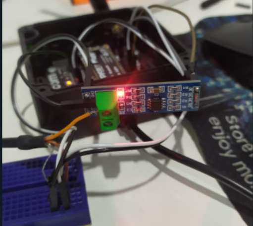
import utime
from machine import Pin, UART, DAC
# from machine import UART

# uart = UART(1, baudrate=1200, pins=('P10','P11'))
uart = UART(1, baudrate=1200)
p_tx = Pin('P3', mode=Pin.OUT)
# p_tx = Pin('P10', mode=Pin.OUT)
p_dir = Pin('P11', mode=Pin.OUT)
# pin12 = Pin('P3', mode=Pin.OUT)
dac = DAC('P21') # create a DAC object


def SDI12(cmd):
    uart.deinit()
    p_tx.value(0)
    p_dir.value(1)                                                          # set output dir
    # utime.sleep_us(12800)                                                   # send BREAK
    utime.sleep_us(14000)
    p_tx.value(1)
    utime.sleep_us(8333)                                                    # send MARK
    uart.init(1200, bits=7, parity=UART.EVEN, stop=1, timeout_chars=75)     # init with given parameters
    uart.write(cmd)                                                         # send command
    utime.sleep_us(8333 * len(cmd))                                         # wait to send command (byte time * command lenght)
    # p_dir.value(0)                                                          # output set to read
    line = uart.readline()                                                  # read data from UART
    return line;

while True:
    print("reading")
    # pin12.value(1)
    dac.write(0.55) # set output to 55% ~1.77V
    utime.sleep(2)
    line = SDI12('?!')
    utime.sleep(3)
    print(line)
    # line = SDI12('0M!')
    # utime.sleep(3)
    # print(line)
    # pin12.value(0)
    utime.sleep(10)
but the response is still "none", and I use rs485 module like this (max485)
-
@Gusti-Made-Arya-Wijaya Compqring with the port of the previous poster, you use different pins for p_tx. In the previous post, p_tx is the same a UART 1 TX, and that is by intention.
-
@Bryan-Hom @robert-hh Hello, I've tried the program and do the wiring diagram like this
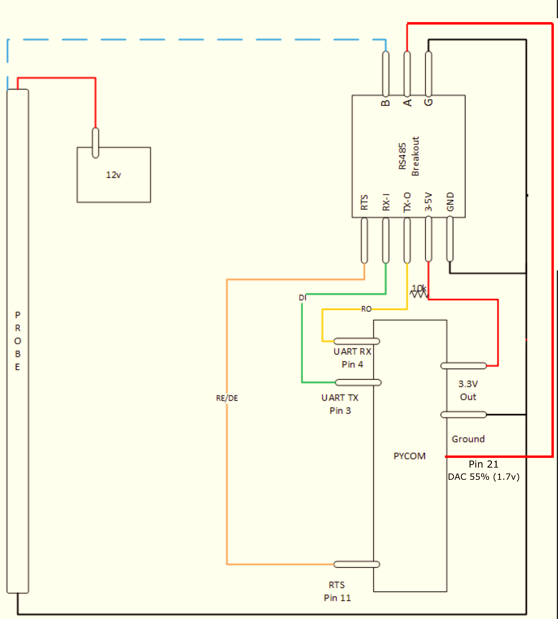
but it still can't seem to get any reply from the sensor.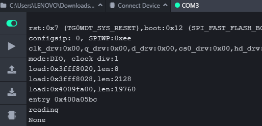 ,
,here is my program
import utime
from machine import Pin, UART, DAC
# from machine import UART

uart = UART(1, baudrate=1200)
p_tx = Pin('P10', mode=Pin.OUT)
p_dir = Pin('P11', mode=Pin.OUT)
pin12 = Pin('P3', mode=Pin.OUT)
dac = DAC('P21') # create a DAC object


def SDI12(cmd):
    uart.deinit()
    p_tx.value(0)
    p_dir.value(1)        # set output dir
    utime.sleep_us(12800)  # send BREAK
    p_tx.value(1)
    utime.sleep_us(8333)   # send MARK
    uart.init(1200, bits=7, parity=UART.EVEN, stop=1, timeout_chars=75)     # init with given parameters
    uart.write(cmd)       # send command
    utime.sleep_us(8333 * len(cmd))  # wait to send command (byte time * command lenght)
    p_dir.value(0)    # output set to read
    line = uart.readline()      # read data from UART
    return line;

while True:
    print("reading")
    pin12.value(1)
    dac.write(0.55) # set output to 55% ~1.77V
    utime.sleep(2)
    line = SDI12("?!")
    utime.sleep(3)
    print(line)
    # pin12.value(0)
    utime.sleep(10)
I need your help to fix it, Thank you
-
@robert-hh Thank you! i rigged up the battery and got the response. I also just tried used a DAC output on Pin22 set at 55% which is roughly 1.77V and it seems to work as well without any special power supply
dac = machine.DAC('P22') # create a DAC object
dac.write(0.55) # set output to 55% ~1.77V
-
@Bryan-Hom Sorry, I misread you diagram. Pin A has to be at a level between 0 and 3.3 V, like 1.8 V in the first diagram. You asked from where to get it, I recommended an 1.8V regulator which in turn gets it power from 5V or 3.3V. For a fist test, you should also be able to use a 1.5V battery.
-
Hi Robert, you seem to be the right person to be asking these questions to, but im using @jimpower's code and i followed the drawing exactly, but i cannot seem to get any reply from the sensor. Probing around my setup it looks like i have all the grounds properly connected, 5v going into to A. I made sure to put the 10k resistor between the 3.3v and the pin 4 (rx) of the pycom. Any thoughts or suggestions? I'm trying to read SDI-12 from a Campbell Scientific AVW200 https://s.campbellsci.com/documents/es/manuals/avw200 - 772.pdf Thank you
import network
import time
import pycom
import machine
import gc
import socket
import utime
from machine import RTC
from machine import ADC
from machine import Pin
from machine import UART


pycom.heartbeat(False)
rtc = RTC()
adc = ADC()
#lora = LoRa()
uart = UART(1, baudrate=1200)
p_tx = Pin('P3', mode=Pin.OUT)
p_dir = Pin('P11', mode=Pin.OUT)


def SDI12(cmd):
    uart.deinit()
    p_tx.value(0)
    p_dir.value(1)                                                          # set output dir
    utime.sleep_us(12500)                                                   # send BREAK
    p_tx.value(1)
    utime.sleep_us(8333)                                                    # send MARK
    uart.init(1200, bits=7, parity=UART.EVEN, stop=1, timeout_chars=75)     # init with given parameters
    uart.write(cmd)                                                         # send command
    utime.sleep_us(8333 * len(cmd))                                               # wait to send command (byte time * command lenght)
    p_dir.value(0)                                                          # output set to read
    line = uart.readline()                                                  # read data from UART
    return line;

time.sleep(2)

while True:

##########################################################
#                   Measure Temperature                  #
##########################################################
    utime.sleep(2)
    command = SDI12('V!')
    utime.sleep(10)
    print(command)                  #Print Sensor Response
    utime.sleep(2)
    command2 = SDI12('0V!')
    utime.sleep(10)
    print(command2)

##########################################################
#                     Garbage Collect                    #
##########################################################
    gc.enable()
    gc.collect()
    print("Sensor Memory Free : " + str(gc.mem_free()))
    time.sleep(15)```
-
This post is deleted!
-
@Bryan-Hom Yes.
-
@robert-hh Thanks, so it should actually look more like this?
-
@Bryan-Hom That's looks wrong. You can consider the 1.8V source as a function block with 3.3V/GND as input and 1.8v/GND as output.
I tried also some other circuits for a SDI-12 connection, but never connected them to real sensors. https://forum.pycom.io/topic/4827/teros-12-and-sdi-12?_=1640181173389
-
@robert-hh Thank you. 1 other question, am i looking at the diagram correctly that the 1.8V + should also be tied in with the 3.3v line? Wouldn't that mean the voltage going into A is 3.3V?
-
@Bryan-Hom Yuo can use a small voltage regulator and derive it from 3.3V. If