Welcome to the Pycom forum Forum
    • \[\[global:header.categories\]\]
    • \[\[global:header.recent\]\]
    • \[\[global:header.tags\]\]
    • \[\[global:header.popular\]\]
    • Login

    Explore Pybytes | Official Documentation | Report a Firmware Bug/Issue | GitHub

    SDI-12 Soil Moisture Probe Help
    Scheduled Pinned Locked Moved LoPy
    sdi-12rs485lopy
    38 Posts 4 Posters 3.3k Views 4 Watching
    Loading More Posts
    • Oldest to Newest
    • Newest to Oldest
    • Most Votes
    Reply
    • Reply as topic
    Log in to reply
    This topic has been deleted. Only users with topic management privileges can see it.
    • J Offline
      jimpower @robert-hh
      last edited by

      @robert-hh

      I'm using an Enviropro EP100G-12 which has 12 rows of sensors at 10cm intervals, each row contains a temp, moisture and ec sensor.

      http://enviroprosoilprobes.com/Files/EnviroPro_SDI-12_CommandsV2.pdf

      http://enviroprosoilprobes.com/Files/EnviroPro_EPCU_User_ManualV3.pdf

      import network
      import time
      import pycom
      import machine
      import gc
      import socket
      import utime
      from machine import RTC
      from machine import ADC
      from machine import Pin
      from machine import UART
      from network import LoRa
      
      execfile('/flash/Network/LoRa.py')
      
      f_device = open('/flash/Config/Device_Details.txt', 'r')
      
      device_setting = f_device.readline()
      device_strings = [i.strip() for i in device_setting.split(',')]
      f_device.close()
      
      pycom.heartbeat(False)
      rtc = RTC()
      adc = ADC()
      lora = LoRa()
      uart = UART(1, baudrate=1200)
      p_tx = Pin('P3', mode=Pin.OUT)
      p_dir = Pin('P11', mode=Pin.OUT)
      
      
      def SDI12(cmd):
          uart.deinit()
          p_tx.value(0)
          p_dir.value(1)                                                          # set output dir
          utime.sleep_us(14000)                                                   # send BREAK
          p_tx.value(1)
          utime.sleep_us(8333)                                                    # send MARK
          uart.init(1200, bits=7, parity=UART.EVEN, stop=1, timeout_chars=75)     # init with given parameters
          uart.write(cmd)                                                         # send command
          utime.sleep_us(8333 * len(cmd))                                         # wait to send command (byte time * command lenght)
          p_dir.value(0)                                                          # output set to read
          line = uart.read(75)                                                   # read data from UART
          return line;
      
      time.sleep(2)
      
      while True:
          batt = adc.channel(attn=1, pin='P16')
          #s = socket.socket(socket.AF_LORA, socket.SOCK_RAW)
          #s.setsockopt(socket.SOL_LORA, socket.SO_DR, 5)
          #s.setblocking(True)
          #s.send("Battery Status : " + str(batt.value()) + " mV")
          #s.setblocking(False)
          print('--------------------------------')
          print("Battery Status     : " + str(batt.value()) + " mV")
          print('--------------------------------')
      ##########################################################
      #                   Measure Temperature                  #
      ##########################################################
          utime.sleep(2)
          line = SDI12('?!')              #Wake Up Sensor
          print(line)                     #Print Sensor Response
          utime.sleep(3)                  #Wait before Next Cmd
          line = SDI12('0C2!')            #Probe Temp Measure
          print(line)                     #Print Time/Sensors
          utime.sleep(5)                  #Wait before Next Cmd
          data = SDI12('0D0!')            #Probe Temp Readings
          print(data)                     #Print Temp Readings
          #utime.sleep(10)
          #data = SDI12('0D1!')            #Probe Temp Readings
          #print(data)                     #Print Temp Readings
      
      ##########################################################
      #                     Garbage Collect                    #
      ##########################################################
          gc.enable()
          gc.collect()
          print("Sensor Memory Free : " + str(gc.mem_free()))
          time.sleep(30)```
      robert-hhR B 2 Replies Last reply Reply Quote 0
      • robert-hhR Offline
        robert-hh @jimpower
        last edited by

        @jimpower Thanks. The code looks principly OK. What happens if you increase the receive timeout?

        The documentation of the product is weird. Why cannot they include a proper protocol definition? Did you see b.t.w. CR/LF transmitted at the end of response messages?

        J 1 Reply Last reply Reply Quote 0
        • J Offline
          jimpower @robert-hh
          last edited by

          @robert-hh

          yes it says technical document "coming soon"

          here is a snippet of my uart.readline()
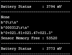
          0_1525864184011_ddb7c828-d942-44ba-9bc5-e1cc5bd7501c-image.png

          Do you think this timeout_chars is correct? I wasn't sure what to put in here.

          uart.init(1200, bits=7, parity=UART.EVEN, stop=1, timeout_chars=75)```
          robert-hhR 1 Reply Last reply Reply Quote 0
          • robert-hhR Offline
            robert-hh @jimpower
            last edited by

            @jimpower SInce the length of the response is not known, you need astrategy to tell when the respons eis complete:

            • either the response has a known terminal symbol, like ! in the command, or \r\n, then you can read until you see that symbol, and wait as second condition for a long timeout. Waitung for \r\n is done by uart.readline().
            • or you have to wait for a timeout.
              The 75 char timeout seems reasonable, but to sort out implementation errors in Micropython, you could increase that for testing and see, if you receive a longer message. Thre reason I ask is, taht I faintly remember some discussion around the rx timeout of uart.read.
            J 1 Reply Last reply Reply Quote 0
            • J Offline
              jimpower @robert-hh
              last edited by

              @robert-hh I'm not sure what happened but I changed my code back to the way it was before playing around with break times, uart timeout etc and it works.
              A note for anyone wanting to interface with SDI-12 with a LoPy you need to perform a gc.collect() after every read and then wait for 30secs before you can read from any other sensors.
              @robert-hh thanks for your help with this it was pivotal to getting a working SDI-12 interface.
              @AntonioValente thanks for your initial concept which lead to this solution.

              1 Reply Last reply Reply Quote 0
              • B Offline
                Bryan Hom @jimpower
                last edited by

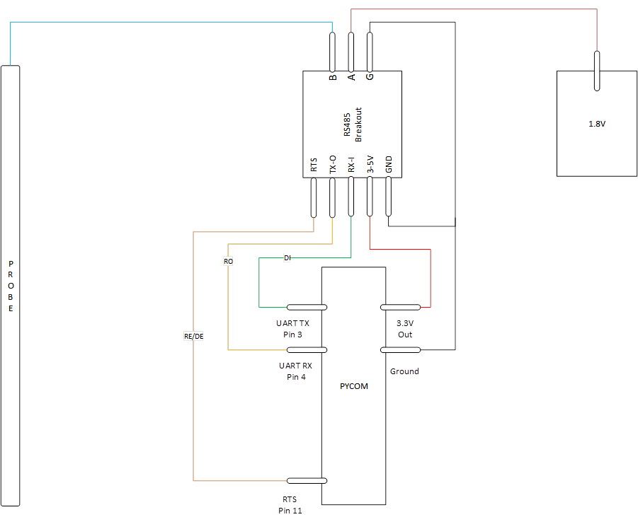
                @jimpower I know this is an old thread but where are you getting the 1.8V ref from?

                robert-hhR 1 Reply Last reply Reply Quote 0
                • robert-hhR Offline
                  robert-hh @Bryan Hom
                  last edited by

                  @Bryan-Hom Yuo can use a small voltage regulator and derive it from 3.3V. If

                  B 1 Reply Last reply Reply Quote 1
                  • B Offline
                    Bryan Hom @robert-hh
                    last edited by

                    @robert-hh Thank you. 1 other question, am i looking at the diagram correctly that the 1.8V + should also be tied in with the 3.3v line? Wouldn't that mean the voltage going into A is 3.3V?

                    robert-hhR 1 Reply Last reply Reply Quote 0
                    • robert-hhR Offline
                      robert-hh @Bryan Hom
                      last edited by robert-hh

                      @Bryan-Hom That's looks wrong. You can consider the 1.8V source as a function block with 3.3V/GND as input and 1.8v/GND as output.

                      I tried also some other circuits for a SDI-12 connection, but never connected them to real sensors. https://forum.pycom.io/topic/4827/teros-12-and-sdi-12?_=1640181173389

                      B 1 Reply Last reply Reply Quote 0
                      • B Offline
                        Bryan Hom @robert-hh
                        last edited by Bryan Hom

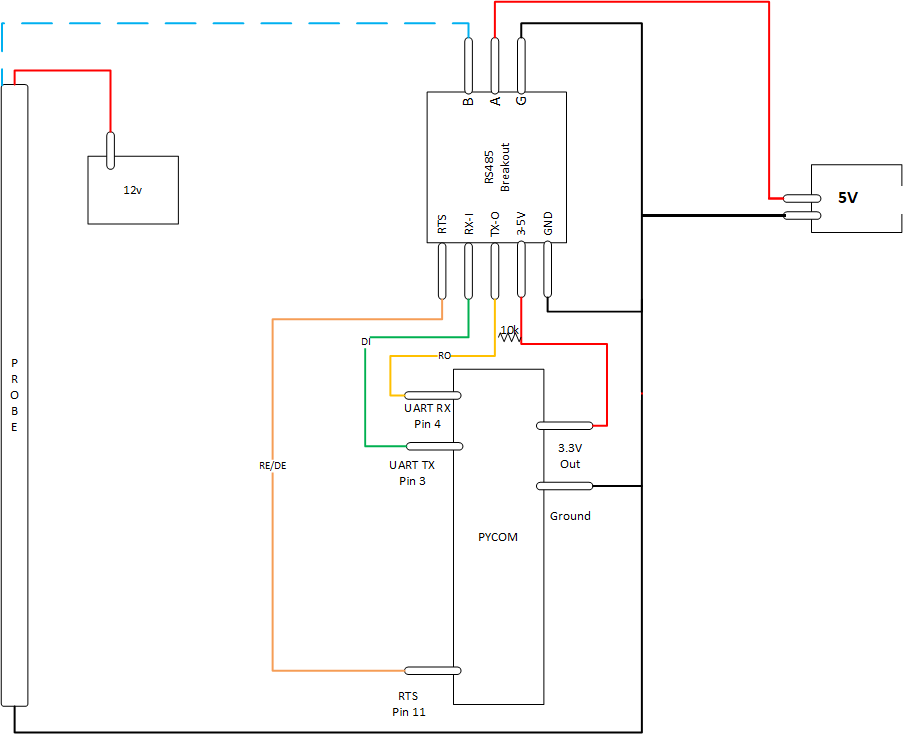
                        @robert-hh Thanks, so it should actually look more like this? pycom SDI-12 schematic.png
                        robert-hhR 1 Reply Last reply Reply Quote 0
                        • robert-hhR Offline
                          robert-hh @Bryan Hom
                          last edited by

                          @Bryan-Hom Yes.

                          B 1 Reply Last reply Reply Quote 1
                          • B Offline
                            Bryan Hom @jimpower
                            last edited by

                            This post is deleted!
                            1 Reply Last reply Reply Quote 0
                            • B Offline
                              Bryan Hom @robert-hh
                              last edited by Bryan Hom

                              @robert-hh

                              Hi Robert, you seem to be the right person to be asking these questions to, but im using @jimpower's code and i followed the drawing exactly, but i cannot seem to get any reply from the sensor. Probing around my setup it looks like i have all the grounds properly connected, 5v going into to A. I made sure to put the 10k resistor between the 3.3v and the pin 4 (rx) of the pycom. Any thoughts or suggestions? I'm trying to read SDI-12 from a Campbell Scientific AVW200 https://s.campbellsci.com/documents/es/manuals/avw200 - 772.pdf Thank you

                              import network
                              import time
                              import pycom
                              import machine
                              import gc
                              import socket
                              import utime
                              from machine import RTC
                              from machine import ADC
                              from machine import Pin
                              from machine import UART
                              
                              
                              pycom.heartbeat(False)
                              rtc = RTC()
                              adc = ADC()
                              #lora = LoRa()
                              uart = UART(1, baudrate=1200)
                              p_tx = Pin('P3', mode=Pin.OUT)
                              p_dir = Pin('P11', mode=Pin.OUT)


                              def SDI12(cmd):
                                  uart.deinit()
                                  p_tx.value(0)
                                  p_dir.value(1)                                                          # set output dir
                                  utime.sleep_us(12500)                                                   # send BREAK
                                  p_tx.value(1)
                                  utime.sleep_us(8333)                                                    # send MARK
                                  uart.init(1200, bits=7, parity=UART.EVEN, stop=1, timeout_chars=75)     # init with given parameters
                                  uart.write(cmd)                                                         # send command
                                  utime.sleep_us(8333 * len(cmd))                                               # wait to send command (byte time * command lenght)
                                  p_dir.value(0)                                                          # output set to read
                                  line = uart.readline()                                                  # read data from UART
                                  return line;
                              
                              time.sleep(2)
                              
                              while True:
                              
                              ##########################################################
                              #                   Measure Temperature                  #
                              ##########################################################
                                  utime.sleep(2)
                                  command = SDI12('V!')
                                  utime.sleep(10)
                                  print(command)                  #Print Sensor Response
                                  utime.sleep(2)
                                  command2 = SDI12('0V!')
                                  utime.sleep(10)
                                  print(command2)
                              
                              ##########################################################
                              #                     Garbage Collect                    #
                              ##########################################################
                                  gc.enable()
                                  gc.collect()
                                  print("Sensor Memory Free : " + str(gc.mem_free()))
                                  time.sleep(15)```
                              robert-hhR 1 Reply Last reply Reply Quote 0
                              • robert-hhR Offline
                                robert-hh @Bryan Hom
                                last edited by

                                @Bryan-Hom Sorry, I misread you diagram. Pin A has to be at a level between 0 and 3.3 V, like 1.8 V in the first diagram. You asked from where to get it, I recommended an 1.8V regulator which in turn gets it power from 5V or 3.3V. For a fist test, you should also be able to use a 1.5V battery.

                                B 1 Reply Last reply Reply Quote 0
                                • B Offline
                                  Bryan Hom @robert-hh
                                  last edited by Bryan Hom

                                  @robert-hh Thank you! i rigged up the battery and got the response. I also just tried used a DAC output on Pin22 set at 55% which is roughly 1.77V and it seems to work as well without any special power supply

                                  dac = machine.DAC('P22') # create a DAC object
                                  dac.write(0.55) # set output to 55% ~1.77V

                                  Gusti Made Arya WijayaG 1 Reply Last reply Reply Quote 0
                                  • Gusti Made Arya WijayaG Offline
                                    Gusti Made Arya Wijaya @Bryan Hom
                                    last edited by

                                    @Bryan-Hom @robert-hh Hello, I've tried the program and do the wiring diagram like this 92a9ee9c-f47d-4a66-96b2-67919c736a7d-image.png
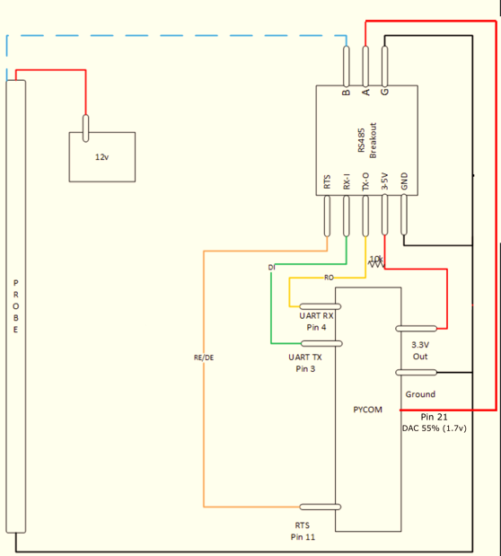
                                    but it still can't seem to get any reply from the sensor. c21d09b0-2608-4452-8b97-02c0342612fa-image.png ,
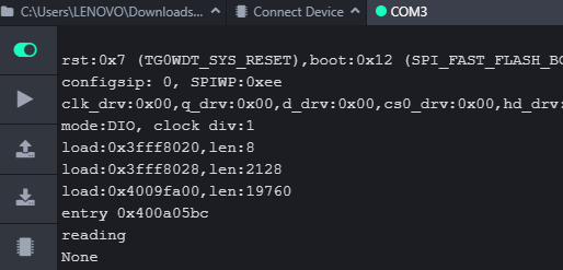
                                    here is my program

                                    import utime
                                    from machine import Pin, UART, DAC
                                    # from machine import UART
                                    
                                    uart = UART(1, baudrate=1200)
                                    p_tx = Pin('P10', mode=Pin.OUT)
                                    p_dir = Pin('P11', mode=Pin.OUT)
                                    pin12 = Pin('P3', mode=Pin.OUT)
                                    dac = DAC('P21') # create a DAC object
                                    
                                    
                                    def SDI12(cmd):
                                        uart.deinit()
                                        p_tx.value(0)
                                        p_dir.value(1)        # set output dir
                                        utime.sleep_us(12800)  # send BREAK
                                        p_tx.value(1)
                                        utime.sleep_us(8333)   # send MARK
                                        uart.init(1200, bits=7, parity=UART.EVEN, stop=1, timeout_chars=75)     # init with given parameters
                                        uart.write(cmd)       # send command
                                        utime.sleep_us(8333 * len(cmd))  # wait to send command (byte time * command lenght)
                                        p_dir.value(0)    # output set to read
                                        line = uart.readline()      # read data from UART
                                        return line;
                                    
                                    while True:
                                        print("reading")
                                        pin12.value(1)
                                        dac.write(0.55) # set output to 55% ~1.77V
                                        utime.sleep(2)
                                        line = SDI12("?!")
                                        utime.sleep(3)
                                        print(line)
                                        # pin12.value(0)
                                        utime.sleep(10)
                                    

                                    I need your help to fix it, Thank you

                                    robert-hhR 1 Reply Last reply Reply Quote 0
                                    • robert-hhR Offline
                                      robert-hh @Gusti Made Arya Wijaya
                                      last edited by

                                      @Gusti-Made-Arya-Wijaya Compqring with the port of the previous poster, you use different pins for p_tx. In the previous post, p_tx is the same a UART 1 TX, and that is by intention.

                                      1 Reply Last reply Reply Quote 0
                                      • Gusti Made Arya WijayaG Offline
                                        Gusti Made Arya Wijaya
                                        last edited by

                                        @robert-hh @Bryan-Hom Hello, I've updated the program like this

                                        import utime
                                        from machine import Pin, UART, DAC
                                        # from machine import UART
                                        
                                        # uart = UART(1, baudrate=1200, pins=('P10','P11'))
                                        uart = UART(1, baudrate=1200)
                                        p_tx = Pin('P3', mode=Pin.OUT)
                                        # p_tx = Pin('P10', mode=Pin.OUT)
                                        p_dir = Pin('P11', mode=Pin.OUT)
                                        # pin12 = Pin('P3', mode=Pin.OUT)
                                        dac = DAC('P21') # create a DAC object
                                        
                                        
                                        def SDI12(cmd):
                                            uart.deinit()
                                            p_tx.value(0)
                                            p_dir.value(1)                                                          # set output dir
                                            # utime.sleep_us(12800)                                                   # send BREAK
                                            utime.sleep_us(14000)
                                            p_tx.value(1)
                                            utime.sleep_us(8333)                                                    # send MARK
                                            uart.init(1200, bits=7, parity=UART.EVEN, stop=1, timeout_chars=75)     # init with given parameters
                                            uart.write(cmd)                                                         # send command
                                            utime.sleep_us(8333 * len(cmd))                                         # wait to send command (byte time * command lenght)
                                            # p_dir.value(0)                                                          # output set to read
                                            line = uart.readline()                                                  # read data from UART
                                            return line;
                                        
                                        while True:
                                            print("reading")
                                            # pin12.value(1)
                                            dac.write(0.55) # set output to 55% ~1.77V
                                            utime.sleep(2)
                                            line = SDI12('?!')
                                            utime.sleep(3)
                                            print(line)
                                            # line = SDI12('0M!')
                                            # utime.sleep(3)
                                            # print(line)
                                            # pin12.value(0)
                                            utime.sleep(10)


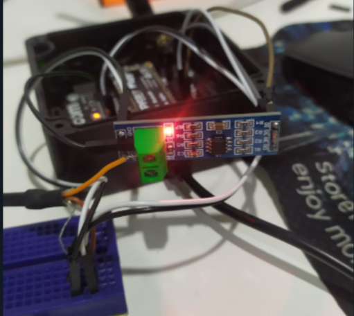
                                        but the response is still "none", and I use rs485 module like this (max485) bcd18c97-3ffa-42df-b85e-63e4417f9e9f-image.png
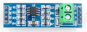
                                        1831e2ea-b977-4ccc-969c-5d53ee43aff6-image.png

                                        robert-hhR B 2 Replies Last reply Reply Quote 0
                                        • robert-hhR Offline
                                          robert-hh @Gusti Made Arya Wijaya
                                          last edited by

                                          @Gusti-Made-Arya-Wijaya As far I see it, the chip has both transmit enable DE and receive enable /RE. For Transmit, the DE has to be high, for receive, the /RE has to be low. Unless you have an inverter connected between DE and /RE, you have to control both in software.

                                          Gusti Made Arya WijayaG 1 Reply Last reply Reply Quote 1
                                          • Gusti Made Arya WijayaG Offline
                                            Gusti Made Arya Wijaya @robert-hh
                                            last edited by

                                            @robert-hh I've followed the wiring by @AntonioValente's reply in https://forum.pycom.io/topic/1924/sdi-12/6 he uses SN65HVD1780 chip that has same pinout as MAX485.


                                            robert-hhR 2 Replies Last reply Reply Quote 0

                                            Hello! It looks like you're interested in this conversation, but you don't have an account yet.

                                            Getting fed up of having to scroll through the same posts each visit? When you register for an account, you'll always come back to exactly where you were before, and choose to be notified of new replies (either via email, or push notification). You'll also be able to save bookmarks and upvote posts to show your appreciation to other community members.

                                            With your input, this post could be even better 💗

                                            Register Login
                                            • 1
                                            • 2
                                            • 2 / 2
                                            • First post
                                              Last post

                                            Pycom on Twitter

                                            Pycom