Current sensor 15A SCT-013
-
Hi,
I bought a current sensor from here. 15A SCT-013
and I made a circuit following this link.below are my current sensor specification:
Model: SCT-013-015
Input current: 0A-15A
Rated output: 15A/1V
Opening size: 13 x 13mm
Output plug: 3.5mm
Dielectric strength: 6000V AC/1min
Mechanical strength: >= 1000 times
Working temperature: -25C ~ +70C(-13F~ +158F)
Cable length: 1.0m
Anti-flaming rate:UL94-V0
Size: 57 x 32 x 21mmI connected the input voltage to 3.3V, GND to GND and analog output to P13 at LoPy. something like this:

my coding as below:
import machine
from machine import ADC
import time

adc = machine.ADC()
apin = adc.channel(pin='P13',attn=ADC.ATTN_11DB)

for i in range(100):
    val = apin()
    print(val)
    time.sleep(1)
but the value I got is random numbers. when no current pass through it will has random numbers, same when current pass through it gets 0. I try connect the input voltage to 5v at LoPy but it is the same. I read a lot of post about sensors connect to LoPy but I cant find current sensor.
Can anyone help? Thank you so much.
-
@StefanoF I made a few more tests with the most recent code I have posted (which is the initial goertzel code).
a) test for phase jitter. Instead of reading the ADC, i just supplied a artificial 50Hz sine with an amplitude of 50 and an offset of range/2 into the algorithm. Result: constant 49.99993, which means that there is no phase jitter.
b) I connected the interface network, but not the sensor. Result: Output values between 0.005 and 0.03. Since the output value of 1Veff is about 240, that is equivalent of ~60µVeff, or about 1 mA through the sensor.
c) connect a battery with 1.5V to the input. Result: values of about 0.5 -> Noisy battery!
d) connect the SCT013 with no current. Value of 0.04 +/- 0.03. That's about 160µVeff of 3 mA (or 0.5 W at 230V) through the sensor. So it looks as if the sensor picks up some noise, but still ok.
e) Using an external ADC (mcp3201). Result: values of 0.05. Slightly worse than using the internal ADC.Lesson learned: I will stick with the initial solution. The challenge is to proper shield the interface network and the cable from picking up unwanted noise.
-
I live in Italy 50 Hz, Thanks a lot
-
@StefanoF Just one question:
are you living in a 50Hz or 60Hz mains region. For 60Hz you have to change the call to Acquire into Acquire(60).
-
@StefanoF I repeated the test with a real current set-up (variable 0..30V transformer and a 1 Ohm load resistor) and the attached script:
at 0 current it outputs. 0.06 +/- 0.3
at ~0.2 A it reports ~2.5
at ~0.5A it reports ~6.9
at 1 A it reports ~13.0
at 2 A it reports ~26.0
at 3 A it reports ~39.0
at 4 A it reports ~52.0
at 5 A it reports ~65
at 6 A it reports ~78.2
at 7A it reports ~92
at 8 A it reports ~105
at 9 A it reports ~118.7
Then the fuse of the 5 A transformer supply tripped in and the load resistor got HOT. No fear. It is an extremely robust supply, used for teaching. And the load resistor is a 50W type with a short time overrating of 250W, surface temperature up to 275°C.
So the values are good in a range from .2 A up. Lower current readings are noisy.# import gc import math import array from utime import sleep_ms, sleep_us from machine import ADC, Timer, idle, enable_irq, disable_irq, Pin # # acquire ADC values. The paramters of the constructor are: # 1. the mains frequency (number, typically 50 or 60) # 2. the sampling period (ms). The default is 2 ms. # class Acquire: def __init__(self, freq=50, *, sample_period=2): self.sample_period = sample_period self.omega = 2.0 * math.pi * freq / (1000 / sample_period) self.coeff = 2.0 * math.cos(self.omega) self.adc = ADC(bits=9) def start(self, pin, time=200): gc.collect() # avoids automatic gc during sampling self.pin_adc = self.adc.channel(pin=pin, attn=ADC.ATTN_11DB) self.samples = time // self.sample_period self.count = 0 self.busy = True self.q1 = 0.0 self.q2 = 0.0 self.alarm = Timer.Alarm(self.read_adc, 0, ms=self.sample_period, periodic=True) def stop(self): self.alarm.cancel() def read_adc(self, alarm): self.q0 = self.pin_adc() + self.coeff * self.q1 - self.q2 self.q2 = self.q1 self.q1 = self.q0 self.count += 1 if self.count >= self.samples: self.alarm.cancel() self.busy = False def result(self): while self.busy == True: sleep_ms(self.sample_period) # amplitude = 2 * math.sqrt(self.q1 * self.q1 + # self.q2 * self.q2 - # self.q1 * self.q2 * self.coeff) / self.count # if phase is required: real = self.q1 - self.q2 * math.cos(self.omega) imag = self.q2 * math.sin(self.omega) amplitude = 2 * math.sqrt(real * real + imag * imag) / self.count phase = math.atan2(real, imag) # return amplitude def reading(self, pin, time): self.start(pin, time) return self.result() # while True: acq = Acquire(50) # 50 Hz value = acq.reading("P13", 1000) print (value)
-
@robert-hh said in Current sensor 15A SCT-013:
Goertze
Many thanks Robert,
I am attaching a files at empty (1.65 volt setoff)
how should I interpret it ?
Goertze.py
-
@StefanoF Here is another code, which uses plain vanilla calc instead of the goertzel algorithm. That is more robust to cumulating rounding errors. I have my doubts about that for goertzel. This also tries to cater for sampling jitter.
#
import gc
import math
import array
from utime import ticks_us, ticks_ms, ticks_diff, sleep_ms
from machine import ADC, Timer, idle, enable_irq, disable_irq

#
# acquire ADC values. The paramters of the constructor are:
# 1. the mains frequency (number, typically 50 or 60)
# 2. the time (ms) for one test period. time must be an integer
#    multiple of frequency period duration and the sampling period
#    being n * 50ms for 60Hz and n * 20ms for 50 Hz. A good value is 200
# 3. the sampling period (ms). time must be an integer multiple
#    of the sampling period. The default is 2.
#
class Acquire:
    def __init__(self, freq=50, *, time=200, sample_rate=2):
        self.sample_rate = sample_rate
        self.samples = time // sample_rate
        self.adc = ADC(bits=12)
        self.freq = freq

        self.data = array.array("f", [0.0 for _ in range(self.samples)])
        pi_f = (2 * math.pi * freq * self.sample_rate) / 1000
        self.timestamp = array.array("L", [0 for _ in range(self.samples)])

    def start(self, pin):
        self.pin_adc = self.adc.channel(pin=pin, attn=ADC.ATTN_11DB)
        self.count = 0
        self.busy = True
        self.alarm = Timer.Alarm(self.read_adc, 0, ms=self.sample_rate, periodic=True)

    def stop(self):
        self.alarm.cancel()

    def read_adc(self, alarm):
        self.data[self.count] = self.pin_adc.value()
        self.timestamp[self.count] = ticks_us()
        self.count += 1
        if self.count >= self.samples:
            self.alarm.cancel()
            self.busy = False

    def result(self):
        while self.busy == True:
            sleep_ms(self.sample_rate)
        # normalize the time stamps
        for _ in range(1, self.count):
            self.timestamp[_] = ticks_diff(self.timestamp[_], self.timestamp[0])
        self.timestamp[0] = 0

        vsin = 0.0
        vcos = 0.0
        pi_f = (2 * math.pi * self.freq) / 1000000
        for _ in range(self.count):
            vsin += self.data[_] * math.sin(self.timestamp[_] * pi_f)
            vcos += self.data[_] * math.cos(self.timestamp[_] * pi_f)
        amplitude = math.sqrt(vsin * vsin + vcos * vcos) / self.count
        gc.collect() # avoids automatic gc during sampling
        return amplitude

    def reading(self, pin):
        self.start(pin)
        return self.result()

def run():

    pin = "P13"
    freq = 50
    meas_time = 1000
    acq = Acquire(freq, time=meas_time)

    try:
        for _ in range(100):
            value = acq.reading(pin)
            print(value)
    except:
        pass
    acq.stop()
    print("Handler stopped")

run()
-
@StefanoF said in Current sensor 15A SCT-013:
EmonLib.h, Emonlib.cpp
I do not know a python implementation for that algorithm. As far as I understand is, if calculates the integral over the zero compensated voltage square. That can be done and may work for strong signals. I expect it to fail for small signals.
-
-
@StefanoF I think your code is not useful. It does not determine the value of the 50HZ AC component. Instead it calculate the average value of a 5ms time window somewhere in the 20ms period of a 50 Hz wave. For a given constant current you will get a largely varying output value, if you repeat the call several time non-synchronous with the mains frequency. And even is the value is in the synchronous case seemingly constant, it may be totally wrong.
I tried similar approaches, e.g. finding the highest and lowest value and then calculating the difference, like a Vpp determination. But that was not robust at all. The only robust approach was using a FFT approach, like the mentioned Goertzel algorithm.
-
Hi Robert,
I've used this my code e variabile ma è valido:
Thanks youdef readACCurrentValue(): global RANGE_AMPS, ADJUST_VOLTAGE peakVoltage = float(0) ACCurrtntValue = float(0) for i in range(5): peakVoltage += apin.voltage() utime.sleep_ms(1) peakVoltage = (peakVoltage / 5) voltageVirtualValue = round(peakVoltage / 1000,2) - 1.65 if(math.fabs(voltageVirtualValue)>0.1): ACCurrtntValue = (math.fabs(voltageVirtualValue) * 15) #15 A return round(ACCurrtntValue,2)
-
@StefanoF You code snippet calculates the average DC voltage at the input. But what you need is the amplitude of the 50 Hz (or 60 Hz) AC voltage. So you have to do some kind of frequency analysis for that frequency. The most simple algorithm for doing that is the so called goertzel algorithm. If you scroll back in this thread, you will find an example which I posted there. I used that and it works fine, except for very small currents. But that is not the problem of the algorithm, that caused by the noise of the ADC capture, both amplitude and phase noise.
-
This post is deleted!
-
StefanoF 2 days ago
Hi ,
I've used this the electronic schema , I've in out 1.65 volt at empty, the sensor is at 15A (STC 013-015)
Can you kindly help me with easy code,apin = adc.channel(pin='P13', attn=ADC.ATTN_11DB) peakVoltage = float(0) ACCurrtntValue = float(0) for i in range(5): peakVoltage += apin.voltage() utime.sleep_ms(1) peakVoltage = (peakVoltage / 5) voltageVirtualValue = (peakVoltage / 1000) print(round(voltageVirtualValue,2))result 1.65
Many thanks
-
@robert-hh Thanks for your suggestion!
-
@StefanoF The schema in your post and the one of Vicky are identical, just differently sketched.
-
@StefanoF They are identical in that they shift up the signal to be measured by Vdd/2. The difference:
- In my schematic the sensor is directly tied to GND, here it is tied to a virtual GND at Vdd/2 with a impedance at 50 Hz of about 30 Ohm.
- I added in my schematics overvoltage protection, which is missing here.
As long as there is no excess current you are try to measure, both will work. In case of a shortage in the sensed circuit, there is a high risk that the connected Pycom device will be damaged.
P.S.: To get a result for measuring, only C1, R1 and R2 are needed in my circuit. Everything else is for protection.
-
Hi,
sorry Robert, because this schema is different of schema di Vicky?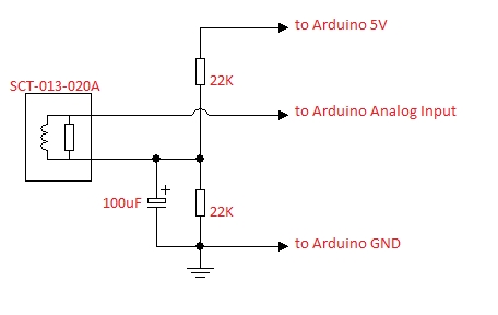 ,,
,,
can you kindly let me know which schema I need used?Many thanks
-
@robert-hh ok thank you so much!
-
@vicky_ in my example, the time for reading is 1000 = 1000ms. If that is too slow, you may take any multiple of 100, like 100, 200, 300, .... instead. Besides that, you can freely select the total measuring time.